|
Class B Amplification: The Latest Development.
Hot on the heels of Quiescent Push-Pull comes Class B amplification, another means of procuring mains volume from the ordinary HT battery. A glance at the power output figures given in this article will reveal the extraordinary efficiency attainable with the new dual valve, no less than two watts speech being delivered to the loud speaker for a surprisingly small HT consumption.
It is safe to predict that Class B output will find wide application in future battery receivers.
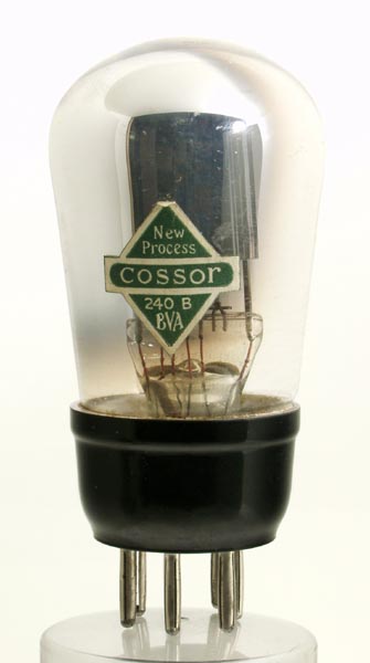
The Cossor 240B as featured below.
Up to the present date two main forms of LF amplification have been available for the battery set user in this country. The first of these is the ordinary form where the output valve is biased to the mid-point of its characteristic. In this case, the anode current drawn from the HT battery is steady and does not vary with the strength of the signal applied. In addition, the maximum signal which the valve will accommodate is limited by the fact that no grid current must flow at any instant.
The second system is that of the well-known form called QPP. Here two valves are used in the output stage, and both of them are supplied with bias sufficient very nearly to cut off the whole of their anode current when no signal is being received. The anode current from the HT battery is now not constant but varies in a manner roughly proportional to the strength of signal received. Here again, however, the maximum signal, which the valve can handle, and, therefore, the available power which it can deliver to the loud speaker, is limited by the fact that grid current must never flow.
Mains Output
In the form of push-pull amplification to be described, which is known in America as Class B amplification, the limitation which is common to the two schemes mentioned above, due to grid current considerations, does not exist. In consequence, the signa1 handling capacity of the valve is unlimited on this score. In addition, the anode current drain on the HT battery is proportional to the strength of signal received, and is not constant irrespective of the signal strength. The net consequence of these two facts is that a system is now available for battery set users which provides an undistorted output of 2 Watts or more with an anode current consumption well within the capacity of quite small HT batteries. Such an output is, of course, equal to that of a large mains set.
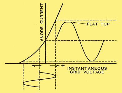
Distortion due to grid current flow in an ordinary LF amplifier. Note the flattening of peaks of the output wave.
The fact that in previous forms of LF amplification the flow of grid current in the amplifying valve means serious distortion, is well known. The exact reason for this distortion is, it is probable, not commonly realised. Grid current in modern valves generally commences to flow when the grid becomes very slightly positive and increases rapidly with increase in positive grid voltage, When such grid current occurs in a set in operation it will, therefore, do so towards the peaks of the positive half-cycles. A high resistance of some form is generally present in the grid circuit of an amplifying valve LF transformer secondary (or resistance in RC coupling), and this current in flowing through such a resistance win entail a drop in voltage. In consequence, when grid current flows, the form of distortion present in ordinary forms of LF amplifiers will be a flattening of the peaks of the waves (see above). Another way of regarding this distortion is to consider that the passage of grid current through the grid circuit entails an energy or wattage loss. This conception leads us at once to Class B amplification, since in this system a small power valve is used which precedes the Class B valve proper, and which is coupled to the latter by means of a special transformer.
The function of this transformer and valve is to supply the energy loss mentioned which occurs due to grid current flow, and thus to maintain the wave form in an undistorted condition. This valve is known as the driver valve, and its associated transformer as the driver transformer.
The Class B valve, which has been designed in the Cossor Valve Laboratories for use in battery sets, has two complete sets of valve elements enclosed in one bulb, separate leads being provided for each anode and grid, the filament connections being common. This has been rendered possible by the fact that matching of the two halves of the output is not at all critical, and thus any slight differences between the two halves due to small inherent manufacturing variations do not introduce audible distortion. The valve has a 7-pin base, with the pins arranged so that it is impossible to make wrong connections with the valve holder.
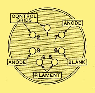
The B7 valve holder connections
The working details of this valve are described later. It is designed in such a fashion, that its anode current at an anode voltage of 120 is about 2 mA at zero bias. In consequence, no grid bias is required to bring the valve to the bottom bend of its characteristic, the point at which it is desired to operate.
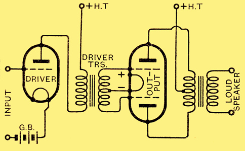
Skeleton circuit diagram of the driver stage linked to Class B output valve. No grid bias is required for the last valve.
Referring to the circuit diagram above it will be seen that if at any instant the grid of one-half of the output valve is positive in respect to the filament, the other grid is negative. Thus grid current is always flowing in either one-half of the secondary of the transformer or the other, and, in general, will cause a voltage drop across that half of the secondary in which it flows, and therefore tends to produce distortion of the peaks of the signal voltage waves. The driver transformer must therefore have a secondary winding of very low DC resistance (good regulation), being wound of wire such as is used in power transformers. The DC resistance of the whole secondary should not exceed in any case 300 Ohms, in order that distortion from this cause may be negligible.
This point is of great importance, and, if it is adhered to, no measurable distortion whatever is introduced at this stage. Except for the design of this transformer, the circuit presents no difficulties. The driver valve is connected as a low-frequency amplifier of the usual conventional type and supplies an undistorted and requisite signal to the Class B valve. The output transformer following the Class B valve has, of course, a centre-tapped primary and is of the correct ratio to give the load into which the Class B valve is designed to work, in relation to the loud speaker impedance.
Since the anode current of the valves passes through the primary of this transformer, and since the peak value of this current may momentarily reach fairly large values; the DC resistance of the primary winding should be small, so as to minimise voltage dropping; 200 to 250 Ohms is a suitable value. For the same reason the core used should be generous in proportions, the primary inductance being of the order of 20 Henrys overall.
Owing to the extreme changes in impedance with frequency of moving iron speakers, these are not recommended for Class B amplification. Permanent magnet moving-coil loud speakers are to be preferred, and, if such can be obtained with high enough voice coil impedances, tapped choke output is recommended. Moving-iron speakers may, however, be used if a tone corrector be applied.
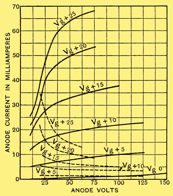
Anode voltage-anode current curves and grid voltage-anode current curves for the two halves of the Class B valve.
The image above gives the anode voltage-anode current curves and grid voltage-anode current curves for the two halves of the Class B valve.
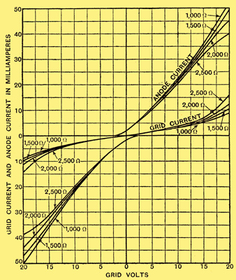
Dynamic curves for the whole valve for various loads taken at an anode voltage of 120.
The figure above shows the derived dynamic curves of the whole valve for various loads, taken at an anode voltage of 120. The peak allowable anode current for the valve is 50 mA, the peak grid voltage for each half being 20 Volts.
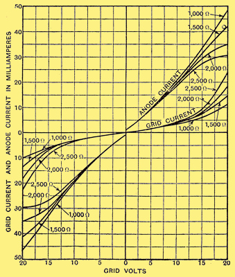
Dynamic curves taken at an anode voltage of 90.
In the next image (above) the anode voltage is 90.
The signal voltage to be supplied to the grids of the Class B valve across the full secondary of the driver transformer may rise to 40 Volts peak. At this point, the lowest impedance is offered by the grid circuit of either half of the Class B valve. This impedance is about 2,500 Ohms, and owing to the fact that only one half of the secondary of the driver transformer is in operation at any moment, the effective minimum load into, which the valve works is 10,000 Ohms if the overall ratio of the driver transformer is 1:1
The energy which has to be supplied by the driver valve to make up for the energy loss due to grid current flow is at this point about 70 milli Watts. This output can well be given by a Cossor 215P valve biased at -9 Volts and with an anode voltage of 120 Volts. Its steady anode current under these conditions will be 2.5 mA.
Two Watts Output
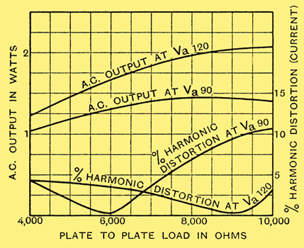
The AC output and percentage harmonic distortion of the Class B valve plotted against anode-to-anode load.
The image above shows the AC output obtained from the valve at anode voltages of 120 and 90 plotted against anode circuit load, together with the percentage corresponding total harmonic distortion, the grid swing being limited to 40 Volts peak. The distortion is almost entirely due to third and odd higher harmonics, as is usual in such forms or push-pull. It will be observed that the optimum load for the valve is about 8,000 Ohms anode-to-anode, and that the AC output obtainable is 2 Watts at a anode voltage of 120.
It would appear at first sight from examination of the valve's dynamic curves that the optimum load is 2,000 Ohms. The discrepancy lies, of course, in the fact that only one half of the output transformer is in use at any instant, and hence a multiplying factor of four has to be introduced giving a anode-to-anode load of 8,000 Ohms. The effect may be well understood by regarding the primary of the output transformer as a kind of auto-transformer.
The comparatively low load of 8,000 Ohms is of great value in output transformer design both regarding cost and efficiency. In itself it would be regarded by many as perhaps the most vital advantage of the system secondary to low anode current consumption for high AC output. There is also, of course, the tremendous advantage of having no bias for the output stage.
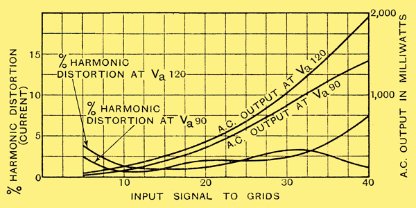
The AC output and percentage harmonic distortion plotted against applied signal in peak volts assuming an anode-to-anode load of 8,000 Ohms.
The diagram above shows the AC output obtainable, and percentage total harmonic distortion plotted against applied signal voltage for anode voltages of 120 and 90 respectively and a load of 8,000 Ohms anode-to-anode. From these curves it will be observed that distortion at low amplitudes is not large enough to cause trouble, and that the lower anode voltage of 90 Volts also gives satisfactorily pure reproduction.
This latter point is of great importance to set designers. The voltage given by the average HT battery after a short period of use, although nominally 120 Volts, is actually below this. In all other systems of push-pull output such a drop in battery voltage would entail the re-adjustment of grid bias (or screen voltage in the case of pentodes) to ensure good quality. If the battery voltage should drop from 120 Volts to 90 Volts distortion becomes by no means intolerable, even though the Class B valve receives its full signal swing obviously, however, its signal drops owing to the lower voltage on the driver valve, and distortion then becomes quite negligible. Since, at the best, adjustment of grid bias or screen voltage in other systems is a delicate matter, the advantage will at once become evident.
Low HT Consumption
The total current drawn by the Class B valve and driver with no signal is, at a anode voltage of 120, of the order of 6.5 mA. This does not represent the total drain on the battery, however, owing to the fact that the valves are effectively working at their bottom bends; the current flowing in the HT battery due to the Class B valve will vary in accordance with the signal applied. These variations will be momentary and will reach the full maximum only when 100 per cent modulation is reached. The average modulation of broadcast stations in general is probably about 25 per cent and this combined with the fact that there are many short periods of rest during a programme will give a very much lower consumption.
Measurements have been carried out using a silver voltameter, of the average current consumed by the Class B valve over a broadcast period of about forty-eight hours of the London National station. The loudest passages were adjusted to swing the grid voltage of the Class B valve to the allowable maximum of 40 Volts peak. Under these conditions, and with an anode voltage of 120, the anode battery drain is 8.5 mA. Thus to obtain an AC output of 2.0 Watts the total HT consumption will be 11.0 mA counting the driver valve current. For lower AC outputs the consumption will, of course, be correspondingly lower.
Some users may find that an AC output of 1 Watt is all that is required to meet their taste. In this case the signal applied to the Class B valve may be limited to a maximum value of 30 Volts peak (grid to grid), and its average anode consumption is 5 to 6 mA. The anode voltage of the driver valve may also be decreased to 100 Volts, giving a current consumption of 1.5 mA. Thus for an AC output stage of 1 Watt the total anode current drain is 6.5 to 7.5 mA, whilst for 2 Watts it is about 11 mA. These figures should be contrasted with the case of a high-efficiency pentode such as the Cossor 220PT, which for an AC output stage of 1 Watt capacity entails a steady anode current drain of 20 mA.
Let us now summarise the great advantages of Class B output. This form of amplification is capable of providing an output from a battery set comparable with that of a mains set, and with an anode current consumption which can be provided by ordinary HT batteries without incurring the disability of short life. Matching of the halves is not critical, and distortion is negligible. No grid bias is required for the output valve, and the output transformer is quite easy to design as the anode-to-anode load is only 8,000 Ohms.
|