|
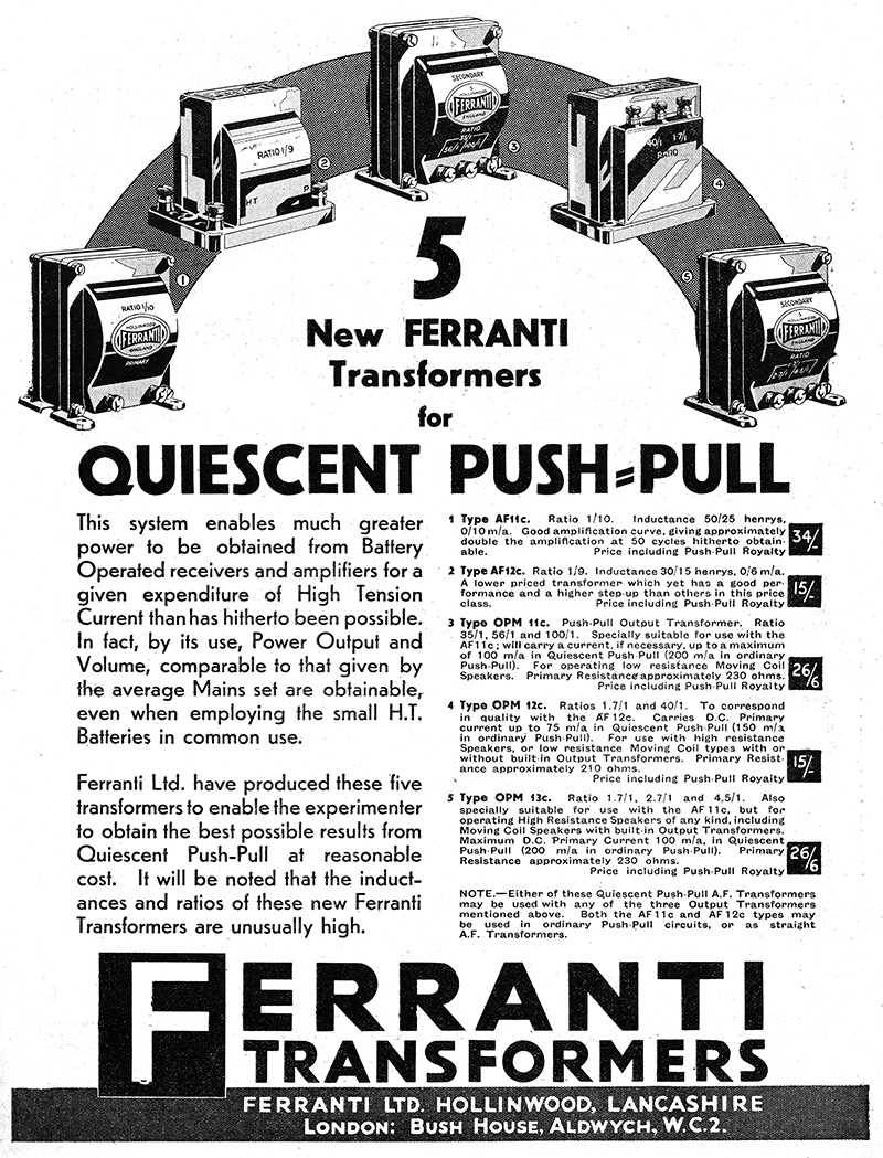
The problem was the need for more output from battery sets without a great increase in the cost of HT battery replacement. For a few years during the early 1930s the answer was proclaimed to be Quiescent Push-Pull (QPP). Designs appeared and specialist components were made.
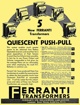
A Ferranti advert from the February 10, 1933 edition of Wireless World.
The steady advance of the National Grid and the development of 'modern' mains-powered superhets meant that the average household radio of the 1930s, especially in later years, could easily provide up to two or three Watts of audio power into a moving-coil loudspeaker of the 'mains-energised' type, which had a sufficiently powerful (electro) magnet to ensure efficient sound reproduction. People not yet supplied with mains electricity had to use battery sets with less efficient loudspeakers. There was thus a demand for much more audio output power than had previously been considered sufficient from battery sets. More powerful battery output valves were therefore made but these, of course, consumed the batteries more quickly.
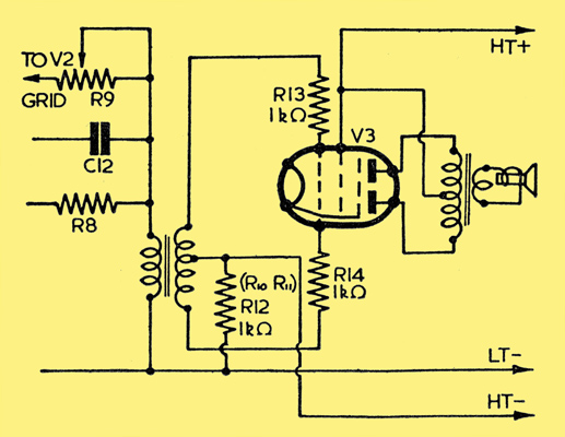
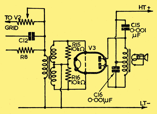
Typical circuit for a double pentode of type KLL35 or possibly the older QP21.
Filament supplies were not the main problem; continuing advances in oxide-coating processes meant that 2V filaments could give more emission without consuming more current. Moreover, the 2V accumulator was normally recharged every week by the local garage for a nominal sum. A few manufacturers tried marketing rechargeable HT batteries but these did not prove a good solution to the problem. Most battery set listeners had to buy a succession of very expensive, non-rechargeable dry HT batteries. Dry batteries did not retain their charge if stored for long periods in hot weather so ensuring that you could obtain a fresh new battery locally at short notice was at least as much of a problem as the cost. It became clear that extra audio power must be obtained without exceeding the current supply capacity of the then industry-standard type of HT battery. However, it was permissible (if necessary) to consume a little extra filament current in order to achieve this.
For a few years during the early 1930s the answer was proclaimed to be Quiescent Push-Pull (QPP). This was essentially Class B with valves biased to almost cut-off but when driven keeping below the onset of grid-current and thus the need for the preceding stage to be able to supply some power. Class B was during the 1930s becoming widely used in high-power audio modulators.
A matched pair of output valves in a push-pull arrangement were biased back so that very little current was drawn under no-signal conditions (Class B1). When a large audio input voltage was applied between the two grids each valve conducted on the positive half-cycles of its input but remained non-conducting on the negative half-cycles. Each valve thus amplified half the signal and the two halves were added together in the correct phase relationship at the push-pull primary winding of the output transformer. Current proportional to the signal was drawn from the battery only when a signal was present and turning down the volume reduced the current drawn. On average, it was possible to have two or three times the apparent volume for the same HT battery drain as the old single valve (Class A) system.
At least, that was the theory and it could be made to work well in professional hands, with well-matched valves and everything adjusted correctly. Unfortunately, it did not work well in cheap sets in the home environment. The grid bias had to be readjusted as the HT battery, or grid bias battery, ran down or the valves wore out and, since this adjustment was rarely if ever skilfully maintained, horrible distortion resulted. QPP quickly got a bad name.
The more enterprising valve manufacturers fought back. Instead of using a pair of ordinary output valves and attempting to adjust the negative bias applied to their grids, special double valves were developed with closely matched characteristics and these were then biased to near cut-off and little or no adjustment was required during use. These valves produced a louder output for a given HT consumption compared to a class A stage but the output was still small.
The next development was the Class B output stage. This used a pair of matched valves within a single envelope designed to operate at 0 Volt bias. However, this meant that the positive half-cycles of the input signal drove the grids positive (Class B2) so that a certain amount of grid current had to be supplied from the previous amplifying stage. In practice this meant an additional valve, or at least a more powerful valve, thus causing additional drain on the HT battery. This system worked rather better than the earlier Class B1 scheme but required an extra valve and, although there was still a net saving of HT current, the saving was rather small compared to the complication and expense. The audio output of up to 2 Watts could match an all mains set for volume.
Cossor made valves for both types of push-pull battery output stages, 240QP for QPP and 240B for Class B.
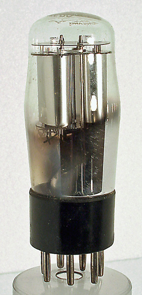
Type KT2 was a valve often used in pairs in Class B1 QPP. KT2s marketed during the brief QPP era are usually marked with a code letter (U to Z) which refers to an adjustment of the G2 voltage supply in order to maintain correct balance and bias conditions. Types QP22B and QP230 (which are equivalents) are examples of specially-developed balanced double valves for Class B1 operation. Type PM2B is an example of a zero-bias Class B2 double valve.
By the end of the 1930s the cannier manufacturers had realised that if you used part of the extra HT and filament current required by the driver valve and applied these resources to power an improved conventional pentode or tetrode output valve, you could do almost as well for half the price, provided the loudspeaker had a reasonably good permanent magnet. Since good loudspeaker magnets were by this time available at competitive prices, this proved to be the answer. By 1939 domestic QPP was passe although Class B2 lived on, and still does, in professional and military applications.
A Class B2 circuit for a Tungsram CB215 or PM2B double triode for up to 1.5 Watts output.
|