|
The conventional method of Class B amplification calls for the use of a special driver stage to make good any losses due to grid current. In this article our contributor describes how it may be possible to produce similar results on entirely different lines.
The distinctive feature of the Class B amplifier, as compared with ordinary push-pull or QPP, is that each valve is driven, in turn, beyond the point where grid current commences to flow.
In the ordinary way, of course, this would at once introduce distortion. In ordinary practice LF valves are always operated with a negative grid bias sufficient to ensure that the working point is always well below that at which grid current sets in.
Generous Power Output
But in applying a strongly negative bias to the grid one naturally increases the internal resistance of the valve, so that it requires a higher plate voltage to produce a given output.
However, this is exactly what we want to avoid, because the particular merit of Class B amplification is that it produces a very generous power output - as much as 2 Watts, if necessary - without requiring a higher plate voltage or taking any more plate current than can be supplied by a dry-cell battery.
In other words, it puts the owner of a battery-driven set on practically the same footing, so far as plenty of undistorted volume is concerned, with the listen.er who has the advantage of being able to run his set from the electric mains.
The objection to grid current in an amplifier may not be very obvious at first sight, but it amounts to this. As soon as the grid becomes positive relatively to the filament, a current commences to flow from the filament on to the grid, and then through the input-transformer windings, back to the filament again.
Voltage Drop
Now a current cannot flow in any circuit without producing a voltage drop across it, and in this particular case, the drop is in opposition to the applied signal voltage. That is to say, the grid does not hold the full signal voltage, but drops a certain fraction - depending in amount upon the impedance of the input circuit - directly grid current sets in.
The result is that the signal voltage is flattened out to a certain extent during each positive half-cycle. During the negative half-cycle nothing of the sort happens, because grid current is not passing. But if two successive half-cycles are treated differently by the valve - one being flattened and the other not - the resulting reproduction must obviously be unbalanced and distorted.
In Class B amplification one gets over this difficulty by using a special driver unit consisting of a valve designed to deliver considerable power into a step-down coupling transformer with a low-impedance secondary. The driver stage supplies sufficient power to the amplifier to make good any losses due to grid current. That, and the special low-impedance input, keeps the signal voltage in proper shape and prevents any flattening effect.
To get the best results it is necessary to use the special driver stage referred to. One might, of course, drive a Class B amplifier direct from a high-impedance detector valve and input, but the power output would fall off, which means that the real advantage of the system is lost.
A Future Possibility
It is perhaps on the cards that some time in the future we may discover a way of simplifying Class B amplification and getting the same results without the additional equipment at present required. But, on the other hand, one seldom gets anything really worth while without having to pay for it, and certainly the extra cost of the driver stage is not excessive.
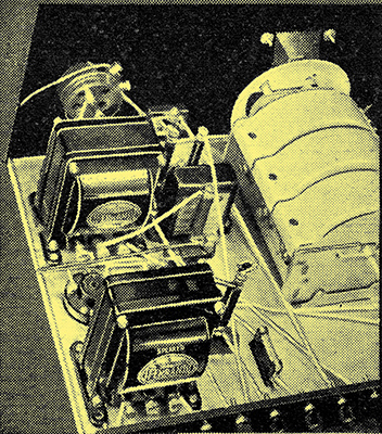
Attempts have, in fact, already been made, particularly in America, to produce similar results to Class B on different lines. One such arrangement is illustrated in Fig. 1.
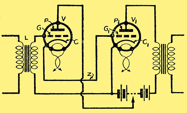
Fig. 1. The valve V1 is the main amplifier, the valve V acting as a grid current compensator thus preventing distortion on the positive grid swings.
The underlying idea is that, as previously explained, grid current distorts one half-cycle of the applied signal, but not the other. If, however, a certain amount of grid current is allowed to pass during each half of the applied signal, i.e. during the negative as well as the positive half-cycle, then one effect could be balanced against the other - leaving the output free from distortion.
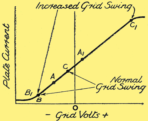
Fig. 2. If the valve could be positively biased so as to increase the available grid swing a considerably greater LFoutput would be obtained.
Granting this to be the case, a much larger output could be obtained. For instance, instead of biasing the grid to the point A, in Fig. 2, and limiting the input voltage to a swing between the points B and C - so as to prevent the grid from going positive - one could choose the point A1 as the initial bias and swing the grid from the point B1 negative to the point C1 positive. Under these circumstances the normal output from a single LF amplifier would be more than doubled.
In the circuit shown in Fig. 1 the valve V1 is the main amplifier, whilst the valve V acts as a compensator for grid current.
It will be noticed that the grid G1 of the main amplifier is connected. directly to the cathode C of the compensating valve, whilst the grid G of the latter is joined to the cathode C1 of the former. Actually the space between the grid and cathode of the valve V forms part of the input circuit of the valve V1.
Ensuring Good Reproduction
When the grid G1 of the amplifier V1 is positive, a small current flows from that grid through the connecting lead Z to the cathode C of the compensating valve. Here it joins the main stream through that valve and returns to the cathode C1 through the HT battery.
On the other hand, when the grid G1 is negative, the cathode C to which it is joined is also negative. That is to say, the grid G is positive relative to its own cathode C. But with a positive grid the valve V naturally passes an extra current, which balances that taken during the preceding half-cycle. In this way the normal cause of distortion is removed, and the amplifier V1 gives true reproduction over a positive grid swing as well as a negative.
|