|
Some refinements and modifications
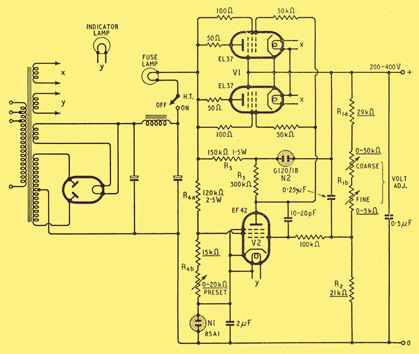
Fig. 7. Circuit diagram of a 200-400 V, 100 mA stabilized power unit as designed. Resistors with values underlined should be wire-wound. A fuse lamp of suitable current rating can be used to give visible warning of load current approaching its permissible maximum.
Previously we discussed the design of series-valve units, illustrating it with an example for providing an output voltage adjustable from 200 to 400 V stabilized against mains fluctuations of +4% to -8% and load fluctuations between zero and maximum, 100 mA. Using a high-gain pentode for output feedback, we found such a unit to be capable of a basic mains-voltage stabilization, even with a source resistance as high as 1000 Ω, of around 280:1, and an internal resistance of a few ohms. By the use of properly adjusted input feedback via the screen-grid, we found it possible not only to neutralize the bad effects of the stabilizing tube resistance, but also to neutralize the source resistance (giving theoretically infinite mains voltage stabilization), or both source resistance and series-valve resistance (giving zero internal resistance), or a compromise between the two.
In relation to its performance, which is amply good for most purposes, the arrangement arrived at so far is quite a simple one. Most of the component values have already been calculated, but there are a few practical details still to be noted.
Applying output feedback by a simple potential divider, ripple in the un-stabilized source is reduced in the same ratio as slow mains fluctuations. It can, as already mentioned, be reduced still more by means of a capacitor across R1. The value is not critical; 0.25 or 0.5 μF is generally satisfactory.
We have a considerable gain in the output feedback loop, and as usual must look out for spurious oscillation. A check on this, and on residual hum, can be made with an oscilloscope connected (with a good blocking capacitor) across the output terminals, using sufficient wide-band amplification to show 1 mV, stray capacitances that would tend to cause phase shift or positive feedback should be avoided and it is wise to screen everything connected to the control grid of V2, especially if the AC power section is on the same chassis. If, in spite of precautions, high-frequency oscillation starts up, add enough capacitance from grid to anode of V2 to stop it; 20 pF should be ample, assuming a grid stopper of about 100 kΩ The gain is thereby considerably reduced at high frequencies, and the internal impedance of the unit correspondingly increased; so it is advisable to provide an HF bypass capacitor across the output terminals, say 0.5 μF
The heaters of V1 and V2 should be connected to their cathodes and fed from separate well-insulated transformer windings.
It will be noted that in the example the maximum Va rating for V2 is liable to be considerably exceeded. In a stabilizer with a high voltage output this is almost inevitable, and does not seem to be a cause of trouble.
For close adjustment of Vo it is a good idea to divide R1b into coarse and fine controls, say 50 kΩ and 5 kΩ respectively.
Gathering all our results together we arrive at the complete circuit diagram, Fig. 7. The rectifier and smoother may be on conventional lines. In this design, little margin has been allowed for tolerances in valves and other components. If it were necessary to ensure effective control over the full working ranges without laboratory checks after renewing valve and neon tubes, and to meet 'commercial' conditions generally, it would be desirable to design rather more conservatively. The rather abnormally high source resistance assumed-1,000 Ω-leaves considerable scope for this, by reducing it.
The observed performance of a unit similar to this one agreed well with expectations. In fact, as regards absence of transients in Vo on suddenly switching the load on and off it exceeded the highest hopes. With R4b critically adjusted, switching 70 mA or so on and off caused only a flicker of the order of 10 mV, or say 1 in 30,000, corresponding to a mean resistance of 1/7 Ω. Larger or smaller load changes, or the same change at a different Vo, without readjustment of R4b, naturally gave less remarkable results, owing to inconstancy of V1a and m, and the reduction of mains fluctuations was only slightly better than 'basic' but that itself was very good. With R4b, critically adjusted for mains stabilization, a sudden mains change of 10% caused, only a momentary flicker of about 15 mV; but that was followed by a slower drift of as 0.8 V due to valve-heaters. Where large fluctuations in mains voltage are liable to occur, a high degree of stabilization can be obtained only by stabilizing the heater supplies too.
Without any exceptional smoothing in the filter, hum was about 1 mV in amplitude; mainly 100 Hz. It depended largely on the layout of the grid circuit of V2. Random noise of 'relatively' high frequency and about 2 mV peak was reduced to a negligible level by 2 μF across N1. The performance of the unit depends largely on this, the voltage standard. Some tubes are liable to 'flicker' every few seconds, as can be seen on the oscilloscope; or they have discontinuities in the characteristics, and may even set up oscillation. The 85A1 has been designed to avoid these defects, and certainly seems very satisfactory.
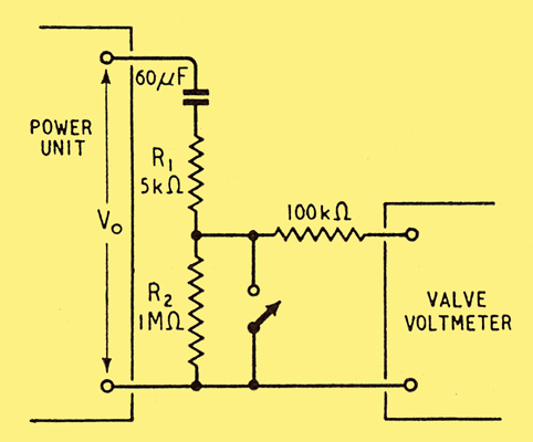
Fig. 8. Method of observing small changes in output voltage Vo.
Incidentally, the method of observing such small Vo fluctuations as 1 in 30,000 may be of interest. A bank of paper capacitors totalling 60 μF, selected for low leakage, was connected across the output as in Fig. 8, in series with a current-limiting resistance R1 and a high resistance R2. The voltage across R2, being the difference between Vo and the practically steady capacitor charge, was observed by a twin-triode ZF voltmeter. Except when actually noting the effects of mains and load changes, R2, was kept shorted by a switch to set the capacitor charge quickly to equality with Vo and to protect the valve voltmeter.
With a fixed compromise setting of R4b the type of circuit described gives a performance which preserves and to a varying extent improves on the basic stabilization conferred by a large amount of output feedback. It is particularly suitable for variable output units, because the input feedback is independent of the setting of the output voltage control. But some alternatives and refinements may fit certain circumstances better.
If N1 can be fed from the stabilized output, there are no appreciable voltage changes across its resistance to be neutralized, assuming the variations in I2k are very small. To retain the use of g2 for neutralizing source resistance, it can still be fed from Vi, but the required value of resistance may be too small by itself to drop the required V2g2 without drawing excessive bleeder current. In such a case a neon tube may supplement it.
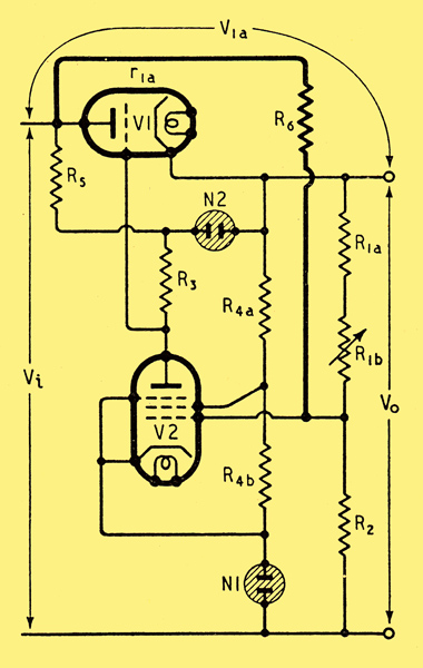
From this, neglecting 1 in comparison with μ1m, we get: R6 = μ1m(R1 R2) = μ1mPoR1, Po being the fraction of Vo applied to the grid of V2.
In the example we have been considering. μ1mPo has been of the order of 500, so if R1 were, say, 60 kΩ, the value R6 required to balance out input fluctuations completely would be of the order of 30 MΩ.
Just as with the feedback via g2 the optimum adjustment of R6 for mains variations is not the same as that for load variations. For when Io changes there is not only a change in Vi due to source resistance Ri, which is neutralized, but in addition a component of change in Via due to valve resistance V1a which is not neutralized, but can be by reducing R6. The system is then somewhat over-stabilized for mains variations (see Appendix, Eqn. 14C in the final instalment), So that changes in Vi cause small changes in Vo of opposite sign.
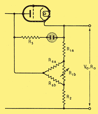
Fig. 10. If R. in Fig. 9 is divided as shown here, the input feedback is rendered independent of R1b the output voltage control.
Unlike feedback to g2 feedback via R6 varies when Vo is adjusted because Pi is a function of R1. Optimum R6 as we have seen, is proportional to PoR1 which is R1 and R2 in parallel. In our example, provision for varying Vo from 200 to 400 V necessitates varying PoR1 in the ratio 1:1.4. The effect of this can be completely avoided by splitting R6 into two, R6a and R6b as in Fig. 10. Suppose Vo is at its minimum with R1b at zero. Then R6a and R6b are directly in parallel, and if their combined value is the same as optimum R6 in Fig. 9, their effect is obviously the same. Also if R6a and R6b are respectively proportional R1a and R2, these four form a balanced Wheatstone bridge, completed via the negligibly low Ro So both ends of R1b are at the same potential as regards input feedback current, and its resistance can therefore be raised to any extent without upsetting the optimum feedback adjustment.
Fulfilling the conditions just stated gives the following values of R6a and R6b for perfect input voltage stabilization: R6a = μ1mR1a and R6b = μ1mR2.
If it is inconvenient to provide such large values of adjustable resistance (of the order of 60 MΩ in our example), they can be stepped down by taking the feedback voltages from an adjustable tapping on R5. Such a tapping also avoids the difficulty of having to vary R6a andR6b simultaneously. But if the latter are below, say, 5 MΩ, it may be necessary to modify the values of R1 and R2 to allow for the current coming from R5.
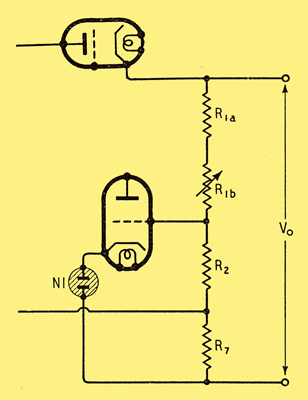
Fig. 11. Output current feedback, normally used together with input voltage feedback, to neutralize the resistance of V1.
All the methods of input feedback described so far have the disadvantage that although they can be adjusted to cancel the residual effects of input voltage changes, or output current changes, they cannot do both completely at the same setting. The former necessitates cancelling the source resistance, Ri. whereas the latter necessitates cancelling the valve resistance, Via, also. The two settings, therefore, are in the ratio Ri:(Ri + Via). If input feedback is set to cancel Ri then it is completely effective against mains fluctuations, and also against that part of the effect of load current fluctuations due to Ri. The effect of Via can be cancelled by feedback from a low resistance, R7, carrying the load current. This device, also described by Lindenhovius and Rinia, is shown in Fig. 11. The voltage change across it, due to changes in load current, when multiplied by R1/(R1 + R2), m and μ1 must be equal and opposite to the voltage change across Via due to approximately the same current. So R7 = (Via(R1 + R2)) / (μ1m R1) = (R1 + R2) / g1mmR1.
If in our example R1 = 60 kΩ, R2 = 21 kΩ, g1m and m = 275, the optimum R7 is 0.41 Ω. If input feedback is not used it should be greater, in the ratio (Ri + Via):Via.
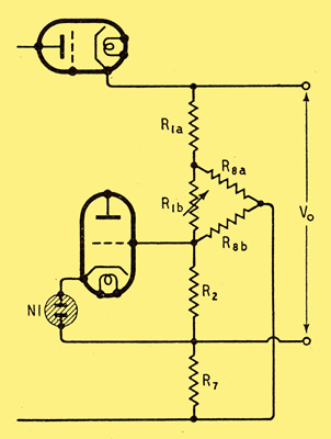
Fig. 12. Modification of Fig. 11 to make it independent of R1b.
To render such feedback independent of R1b adjustments, the analogous arrangement to Fig. 10 is shown in Fig. 12. It will be shown (Appendix, Eqn. 18) that the appropriate values for R8a and R8b are: R8a = g1mmR7R1a, R8b = g1mmR7R2.
To avoid upsetting the R1R2 potential divider unduly, R7 should be as large as can be tolerated, say 100 Ω.
Fig. 10 and Fig. 12 can be combined. In seeking thus for more and more perfect stabilization, the fact that these critical balances depend on other variable factors must not be forgotten. We saw from Fig. 5 how the gain, m, can not only be much increased (giving greater basic stabilization) but also made far more constant (which we now see enables 'perfecting' feedback to be applied more effectively over a wide range of output voltage) by the use of N2. Most of the optimum values for supplementary feedbacks depend on g1mm or Via/m. This is fortunate, because the remaining inequality in m tends to be offset by simultaneous changes in g1mm or Via. So although it is possible to render m practically constant over a wide range of I2a by using a suitable non-linear resistor for R3 the overall result is likely to be worse, especially as m is inevitably less with such a resistor owing to its AC resistance being lower than the DC
For a flexible-output unit such as Fig. 7, input feedback would conveniently be via g2, rather than R6 ; but if it were important to stabilize very thoroughly against both mains and load fluctuations it might be well worth while to add Fig. 12. and, if mains fluctuations were large and more than momentary, to stabilize the heater voltages.
Part 1 Part 3
|