|
(1) Laying Out and Preparing the Ebonite Panel.
Procure a piece of ebonite 8 x 5 x ¼ inches thick, and carefully smooth and square-up with a fine file. Remove all polish by rubbing with pumice powder and oil. A good method to lay out the panel: paste a piece of paper on underside of panel and mark out drilling points VERY CAREFULLY with a sharp pointed pencil, as shown in the illustration. When drilling is completed remove paper with warm water. This illustration shows all drilling points with the exception of valveholder which is explained on card (3).
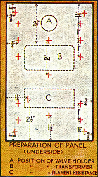
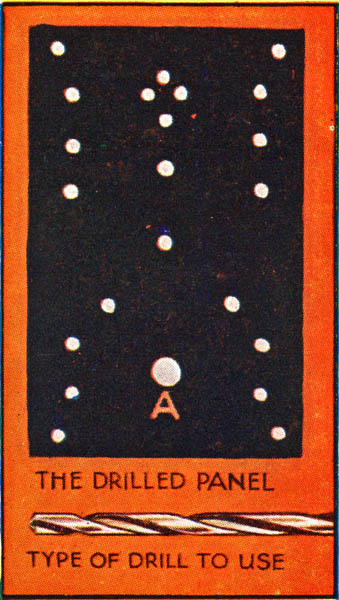
(2) Drilling Panel.
Drill out all the holes very carefully with a twist drill. All the holes are drilled to take 4 BA screws with the single exception of the hole marked 'A', which is drilled to take a brass collar or bush through which the screwed rod of the filament resistance is passed. One hole will be noticed in each corner for the wood screws which fasten the panel to the cabinet. Always drill from the face side of the panel, and be very careful not to split the ebonite. NB - Keep drill square with panel when working.
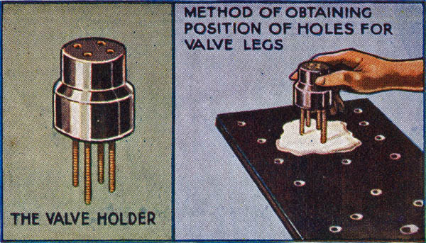
(3) The Valve Holder.
In order to save trouble when drilling the panel, it is much better to purchase a valve holder as illustrated. This fitment has four sockets in which the four legs of the valve fit accurately.
To Drill Panel. - Pour on to the underside of panel, just about where the valve holder is to be mounted, molten paraffin wax or candle grease. When still warm press the four legs of the valve holder onto the wax - See illustrations. Drill panel at these points, and the four legs will drop exactly into place.
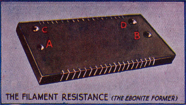
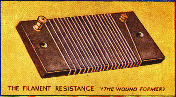
(4) The Filament Resistance.
Preparing ebonite former: - Procure a piece of ebonite 3 x 1½ x ¼ inches thick and carefully smooth up with a fine file, finishing off with pumice powder and oil. Drill two 2 BA holes at A & B so that the resistance may be mounted to the panel by means of two counter-sunk screws passed through the ebonite former and the holes previously drilled in panel, the whole secured with two nuts. Bore top two holes at C & D size 2 BA. With a hack-saw cut 20 slots on each edge of former as shown.
(5) The Filament Resistance - Winding the Ebonite Former.
Three yards of 22 SWG Eureka resistance wire are required. Start at C and secure one end of wire to a terminal screwed into the bored and tapped hole described on card (4). Carefully wind the wire round the former so that the turns fall into the slots until the winding is completed. Secure other end of wire to a cheese headed screw which is screwed into hole D. The wire is wound tightly so that every turn lies absolutely flat on the face of the ebonite former.
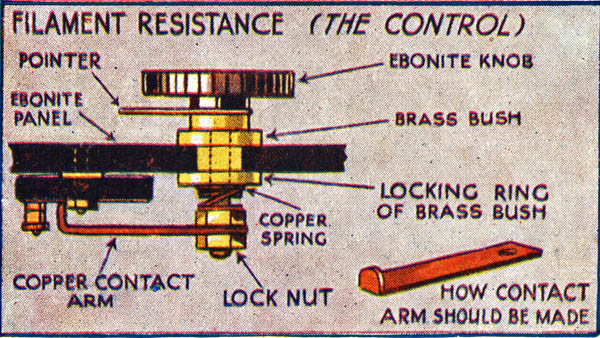
(6) The Filament Resistance - Contact Arm.
The following components are required: One ebonite knob and pointer; brass collar or bush; one small copper spring; two or three copper nuts and also a copper contact strip. This is made by cutting out from a piece of sheet copper a strip one inch wide and bending into shape illustrated with a pair of pliers. This strip is gripped tightly between two nuts, and locked with a third if necessary and is so arranged that when the knob is turned the contact slides firmly over the whole face of the resistance wire.
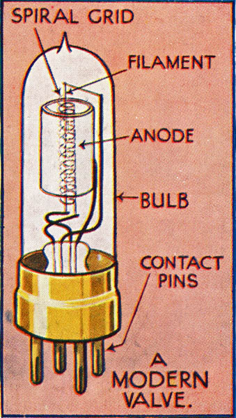
(7) Type of Valve.
The honour of discovering the valuable properties of the thermionic valve belongs to Dr. Fleming, but a very considerable improvement was effected by Dr. Lee de Forest, who introduced what is known as the grid between the filament and the anode. The universal use of this type of valve is due to its power of amplifying the incoming signals when suitably connected and thus increasing the volume of sound heard in the receiver. The illustration on this card gives the details of a modern valve.
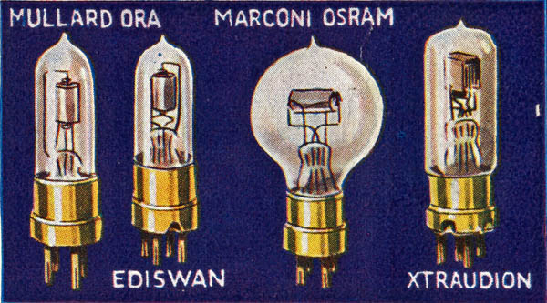
(8) Types of Valve.
On this card are illustrated four types of valves now in constant use and proved to give first-class results. Great care in handling the valve is necessary. Do not jolt them or the filament resistance may break and thus put the valve out of commission. The filament after some use is inclined to sag and touch the grid. This, of course, ruins the valve. It is therefore better to purchase a valve with a vertical filament.
Examples of suitable valves are:- Mullard ORA, Ediswan AR, Marconi R, Cossor P1 and Cosmos A45.
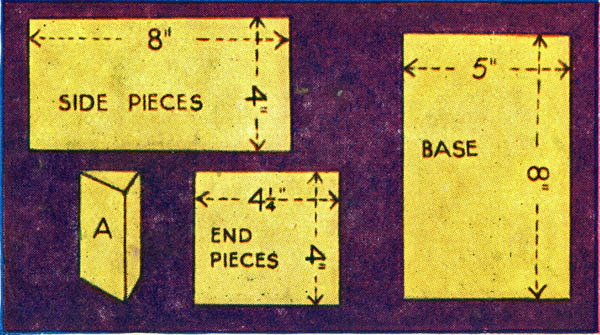
(9) Layout of Cabinet.
The cabinet should be made up from ⅜ inch material. The wood may be of any kind to suit your individual choice; white wood - stained, varnished or polished may be used if preferred. The two side pieces are cut 8 x 4 inches, the two end pieces 4¼ x 4 inches, and the base 8 x 5 inches. Four triangular pieces as A are cut for strengthening the corners of the box, thus ensuring the wood not splitting when the panel is screwed to the cabinet.
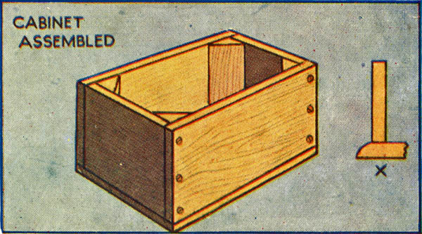
(10) Cabinet Assembled.
The illustration shows the cabinet completed. Brass wood screws are used throughout, and when driving the screws home care should be exercised so that the screws go into the wood perfectly straight and equidistant from either face, otherwise splitting will result. Three screws driven in as indicated at each corner, the base secures by screws (two on each side) and the corner pieces glued into position will produce a sturdy workmanlike cabinet. Finish cabinet to suit individual taste. Base may be made ½ inch larger all round and bevelled as X if desired.
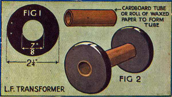
(11) The LF Transformer - The Former.
From a piece of ¼ inch ebonite cut two circular discs (Fig. 1) each disc having a diameter of 2¼ inches. Carefully smooth with a fine file. At the exact centres of the disc drill a 7/8 inch hole, also two small holes with chamfered edges through which are passed the leads from the transformer windings. Cut 2 inches off a piece of cardboard tube which gives a tight fit in the central holes of the discs and fasten with liquid glue (Fig. 2). The cardboard is now covered with a good coating of shellac and allowed to dry.
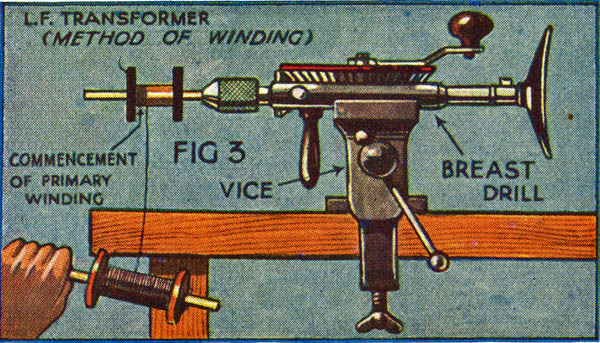
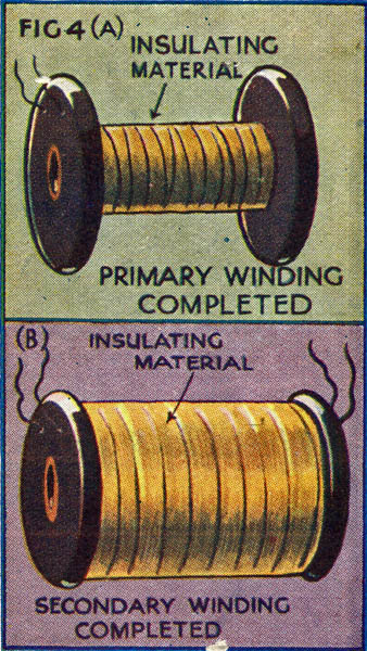
(12) The LF Transformer - Primary Winding.
Take the former explained on card (11) and mount conveniently (Fig 3) to facilitate the winding-on of the primary of the transformer. ½: lb of No. 42 single silk covered wire is required. One end is is threaded through one of the small holes and about 50 turns are wound on to the former: cover with shellac and allow to dry, but do not break the wire. Now continue to wind on the wire evenly and firmly until about 2,500 turns are on the former. Cut wire and thread through the other hole in the same disc as indicated in (Fig. 4a) on card (13).
(13) The LF Transformer - Secondary Winding.
Cover the primary already explained on Card (12) with two layers of Empire tape or Waxed Cartridge Paper and fasten down with thick shellac (Fig. 4a). It is very essential that no electrical leakage should occur between the two windings. Now wind on the secondary in the same manner as the primary (explained on card number (12)), but this time about 6,000 turns should be wound. This is the secondary of the transformer and this winding is covered with Empire tape or Waxed Cartridge Paper (Fig. 4b).
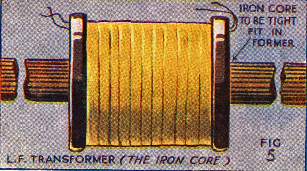
(14) The LF Transformer - The Iron Core.
Procure about one lb. of No. 22 or 24 Soft Iron Wire and cut up into about ten inch lengths. Now make a bundle of these lengths so that they make a tight fit when inserted through the cardboard tube of the former (Fig. 5) after insertion in the former, car should be taken to see that the overlap of wire on each side of the former is the same. Also, be very careful to procure SOFT Iron Wire - this is essential.
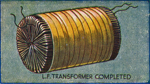
(15) The LF Transformer - Completed.
To the four ends of wire now protruding solder short lengths of stouter wire ('flex' will do) and secure with adhesive tape so that the fine wire is not broken when connecting up. Bend iron wires back over the transformer as indicated, leaving the flexible wire free. The wire thus bent back may be secured in position by winding tightly over the two layers of adhesive tape. The completed transformer should now appear as the illustration.
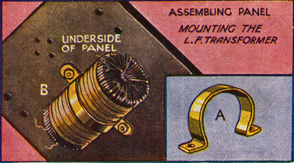
(16) Assembling Panel - Part One.
Place the four legs of the valve holder in the holes and secure to panel with the small nuts provided with the holder. Ten 4 BA terminals are secured to the panel in like manner.
In order to mount the LF Transformer cut a strip of brass about ½ inch wide and a suitable length to go round the transformer. At each end drill a four BA hole and bend back as indicated (A). It may then be securely fastened to panel with two countersunk screws and two nuts (B).
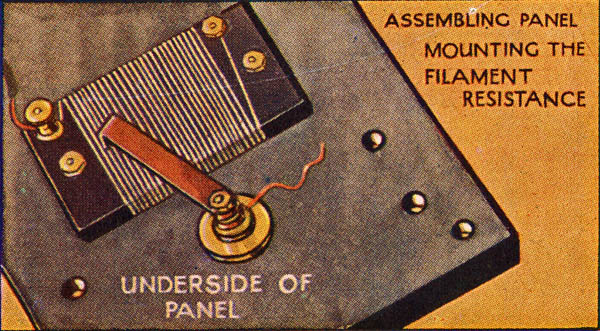
(17) Assembling Panel - Part Two.
The wound resistance former is secured to the panel by means of two countersunk 4 BA screws passed through the panel from the face and through the holes drilled in the ebonite former; the whole tightened by means of the two nuts. Secure collar of sliding contact to panel and mount the remaining components as indicated. A short piece of flexible wire is secured between the two nuts so that contact may be effected with one of the accumulator terminals.
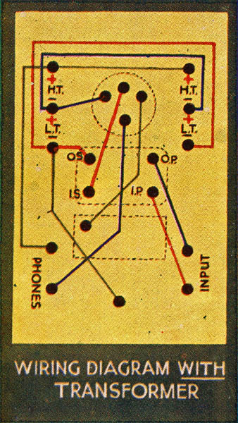
(18) Wiring Up - With LF Traansformer.
The wiring up of the panel is a comparatively easy matter and needs little explanation. Copper wire not less than 18 gauge should be used throughout with the exception of the flexible wire which connects moving unit of the filament resistance to the negative termimal of the accumulator. Every wire must be carefully insulated so that no electrical connection can occur between the various wires. Work neatly and be sure that all nuts are screwed tightly, otherwise loose connections will result.
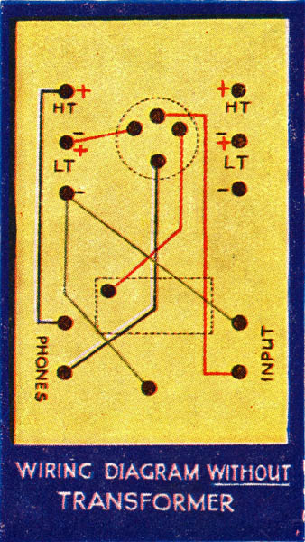
(19) Wiring Up - Without LF Transformer.
This circuit does not give such excellent results as the circuit employing an 'input' or LF transformer, but certainly strengthens the signals given by the crystal set. In the diagram, each wire is distinguished by its separate colour, and only makes connection at the points indicated by the black dots. It will be noticed that we are only using one set of battery terminals; as the effect of coupling a series of units of this sort gives very poor results in comparison with the transformer circuit previously mentioned.
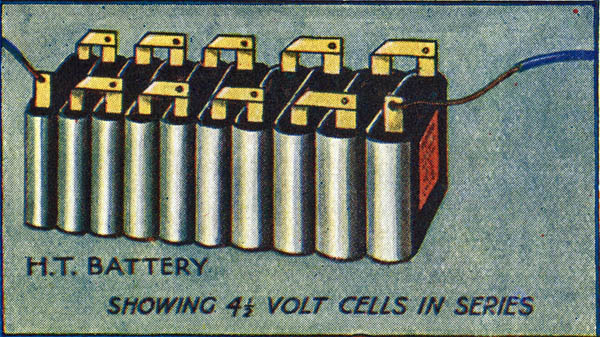
(20) The HT Battery.
This may be purchased either as a single unit, giving up to the required voltage, or may be composed of a number of 4½ volt cells (pocket flash-lamp batteries) connected in series. We prefer the latter method, because, should a battery become useless by corrosion or any other reason, it may be removed and another substituted. A good battery is essential, otherwise crackling and other unpleasant noises may be produced in the telephone receivers; cells should be tested with a voltmeter before purchasing.
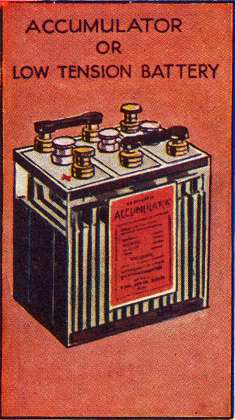
(21) Accumulator or LT Battery.
If a single valve is to be used we recommend a 4 volt cell of fair ampere-hour capacity, but if a number of units are contemplated we suggest that a 6 volt battery be employed. Always work your valve at the lowest filament voltage. LT batteries require considerable attention to keep them in good order and we recommend that a proper battery service station be employed to keep them charged and in good condition. When purchasing your battery get a good make - it is cheaper in the long run.
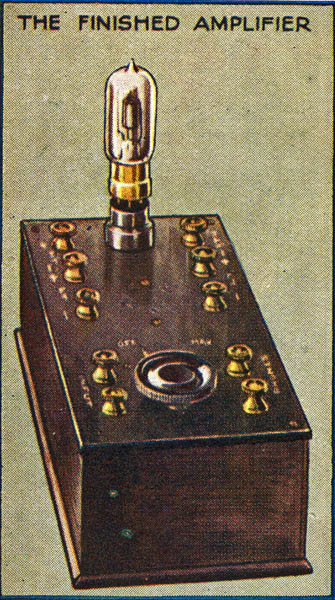
(22) The Finished Amplifier.
When the Amplifier is fully completed and all the components mounted, and the panel is screwed down to the cabinet, it should appear as the illustration.
To OPERATE - After connecting to crystal set (See card (23)) adjust crystal set and turn the knob of filament resistance when the valve will light up. Adjust both the voltage of the HT battery and accumulator until the incoming signal has developed its greatest amplification.
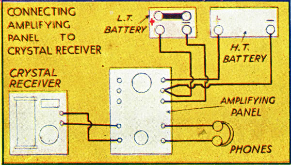
(23) Connecting Set to Crystal Receiver.
From the right hand telephone terminal on the BDV Crystal Receiver take a wire to the bottom terminal of the two marked 'input' on the amplifying panel. The remaining telephone terminal is then connected to the remaining 'input' terminal. Connect HT battery to HT terminals (+ to + and - to -) and accumulator to LT terminals (+ to + and - to -).
The telephone receivers are secured to the terminals marked 'phones' on the panel.
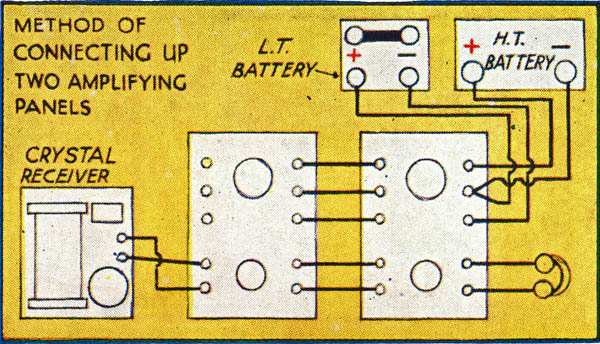
(24) How to Connect Two Panels.
This panel has been so designed that further units may be added if desired, in order that still greater amplification of the incoming signals may be obtained. These units are constructed in exactly the same manner as the one in this series, and five short lengths of insulated wire are used to bridge the two units. Thus, the HT battery and accumulator are connected as indicated while the 'phone' terminals on panel number one are connected to the 'input' terminals on panel two.
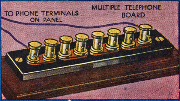
(25) Connecting More Than One Pair of Phones.
Prepare a strip of ebonite 4½ x 1 inch wide and drill eight holes in which are inserted eight 4 BA terminals. Small lengths of copper strip are attached to these terminals so that Nos. 1 & 2, 3 & 4, 5 & 6, 7 & 8 are connected together. Secure this panel to a base-board by a wood screw at holes A & B as indicated. Connect phone terminal of panel to terminals 1 & 8, and three pairs of telephones may be inserted between terminals 2 & 3, 4 & 5, 6 & 7. For two pairs of phones connect set to terminals 1 & 6.
|