|
The MZ2-200 directly heated triode was designed for use as a high level audio modulator for amplitude modulated transmitters. Such a device was also perfectly good for high power audio amplifier use.
Mullard published a design for a high power amplifier. A pair of the MZ2-200's were driven by a pair of EL37's. The amplifier operated in class AB2 push-pull, the driver stages are cathode followers and are directly coupled to the power valves.
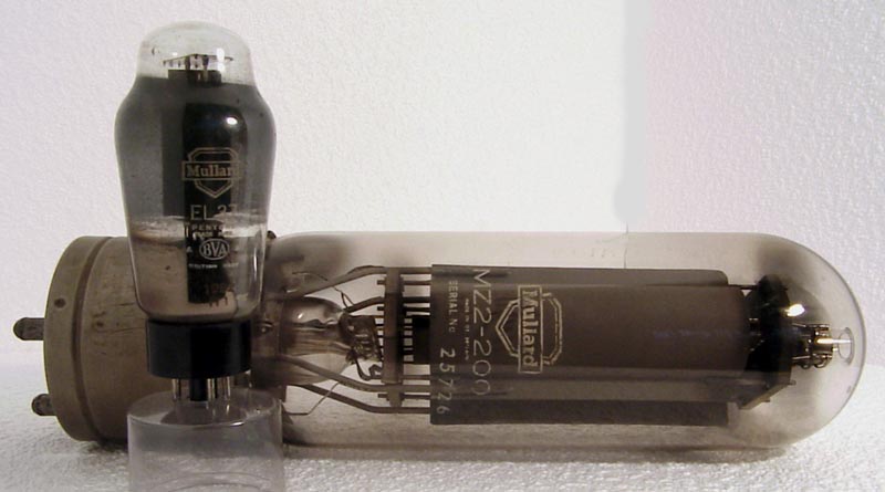
A comparison of the valve sizes is shown. When taken with the massive transformers and chokes for the power suppliers, and output transformers. It is possible to visualise the completed amplifier as a cabinet mounted assembly on at least two chassis.
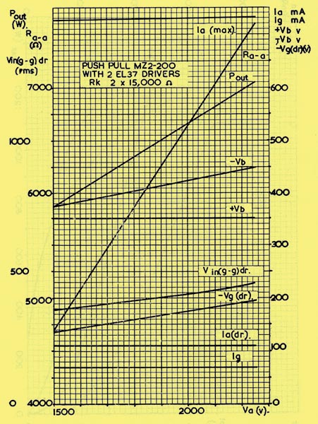
The amplifier can be used for a range of outputs from 746 Watts to 1,213 Watts depending on anode voltages.
The MZ2-200 anode voltages can range from 1.5 kV to 2.25 kV in the circuit presented.
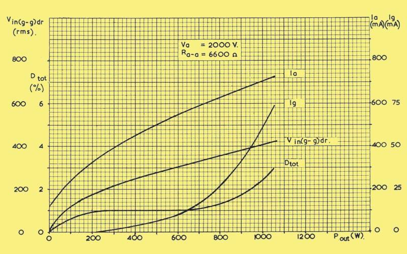
The total distortion remains around the 3% mark in all cases of the maximum power output.
The build would require high stability wire-wound resistors and potentiometers. In view of the lethal voltages and currents, a high degree of shielding and insulation would be mandatory.
The main rectifiers would be significant components in their own right, and the HT capacitors would be substantial metal cans.
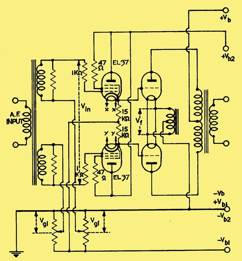
For a 1 kW amplifier the parameters are as follows. Anode voltage 2.0 kV, anode current 2 x 60 mA quiescent - 2 x 363 mA full output. Peak grid current 2 x 36 mA. Anode to anode resistance 6,600 Ohms. Output power 1,048 Watts at 2.9% distortion. The driver stage conditions are Vb1 at - 425 Volts, Vb2 350 Volts, Vg1 - 176 Volts. The quiescent anode current for the EL37's would be 2 x 20.5 mA, and peak anode current 2 x 56.5 mA. The input voltage is 2 x 207 volts RMS. The input voltage for the MZ2-200 is 0.9 of Vin of the driver.
The regulation of the bias rail is not critical, and a capacitance input filter can be used. The driver supply and the main HT should be fed from a choke input filter.
With no signal input, the bias potentiometers should be adjusted to set the anode currents of the corresponding output valves at the specified no signal values. The correct driver conditions will then be automatically secured by the specified values of components and supply voltages.
The heaters xx and yy must be supplied from separate windings on the mains transformer. The output valves have the filaments specially supplied.
|