|
A design that made it to production.
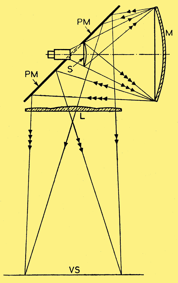
In order to make the most effective use of the light available from the fluorescent screens of a cathode-ray television receiver, it is collected by a concave mirror M which projects it back on to a plane mirror PM having a central aperture in which the fluorescent screen is located. The plane mirror is arranged at such an angle, say 45 °, that none of the light reflected by it can reach the concave mirror, but passes, as shown by the arrows, directly on to the viewing screen VS.
In order to minimise spherical aberration and similar optical troubles, a 'correcting' lens L is interposed between the mirror PM and the viewing screen. Various positions of the mirror PM are possible, but an analysis shows that the one in which it is tangential to the upper periphery of the fluorescent screen, as indicated in the drawing, is the most effective.
Philips Lamps, Ltd. (Communicated by N V Philips Gloeilampenfabrieken). Application date January 12th, 1942. No. 548,750.
|