|
Projection television receivers have been on the home market for some appreciable time, and many will be interested in the novel optical system used to give the large picture on the flat screen. The cathode ray tube employed is much smaller than that of the more orthodox receivers, and this is claimed to offer several benefits economically and technically.
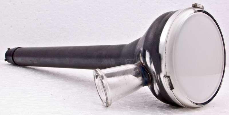
The Mullard / Philips MW6/2 projection tube.
It may be convenient here to discuss some of the points which the manufacturers of projection television receivers claim for the small cathode ray tube as against the large one, and then show how the picture on the screen of the small tube is optically enlarged.
The television receivers of the orthodox type are arranged for 'direct view', and these have claimed the publics attention, in the main, from about 1936 to date. The image observed is the actual image formed on the luminescent screen of the cathode ray tube. Mechanical problems are involved in designing a tube of the orthodox pattern which will have a flat plane screen surface to withstand the pressure of the atmosphere and resist implosion. For example, the tubes of screen diameter over 15 inches have to withstand forces in excess of 2,000 lb. The tubes must be of thick wall structure and curved on the screen face with attendant image distortion on the screen. Further, tube length increases with screen diameter and the cabinet volume has to be much enlarged to accommodate the extra length, often to objectionable proportions. Alternatively, the scanning angle may be enlarged, but this introduces design problems of its own.
The projection method obviates these objections by the simple expedient of using a small cathode ray tube, and projecting the small image on to a viewing screen much as in the well known cinema layout, This is not meant to imply that the projection method is not suitable for the home; for it is in this field that it has the maximum appeal in that the family can sit back and regard a screen of comfortable proportions and unrestricted view. This entire article is directed toward the home receiver.
As long ago as 1937 Wolf [1] Enlarged Projection of Television Pictures. M Wolf. Philips Tech. Review, Vol. 2 1937, p.249. had discussed the contours of cathode ray tubes of diverse diameters, showing the curvature of screen which could be tolerated from the standpoint of glass technology and its effect upon picture area. He proposed a projection of the picture on the fluorescent screen of a small cathode ray tube on to a large ground glass screen of, say, 100 x 120 cm, using an optical system.
The optical system suggested was a projection lens with a relative aperture of 1/1.9, and the cathode ray tube had a concave screen surface having a curvature corresponding with the curvature of the lens image surface to facilitate the production of a plane screen image on the projection screen. This idea has, however, developed along unusual lines from Wolfs suggestions when we consider the optical system in favour at the present time.
It was fairly obvious that a lens such as Wolf proposed could be utilised, but the other classical method for image production was the well known spherical mirror. To decide which of the two, lens or mirror, was preferable necessitated an analysis of the physical properties of each.
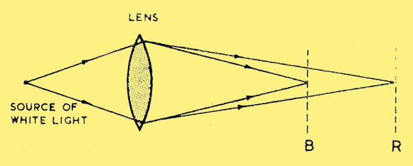
Figure 1
The analysis is briefly as follows: Lenses suffer from chromatic aberration, that is to say white light passing through a lens causes the blue rays to come to a focus at B, Fig. 1 above, and the red rays at R, the glass having a greater refractive index for the blue rays than for the red. The other colours will have foci at intermediate points. Chromatic aberration may be corrected by an achromatic system for selected conditions. However, lens systems of large aperture, as needed in projection television, raise other complex problems with regard to coma, spherical aberration, astigmatism and distortion. A consideration of these complexities is outside the scope of this article, and interested readers are referred to the erudite works of Conrady [2] The Five Aberrations of Lens Systems. A E Conrady. Monthly Not. Roy. Astron. Soc. 79. 60-66. 1918. and de Groot [3] Optical Aberrations in Lens and Mirror Systems. W de Groot. Philips Tech. Review. Vol. 9, 1947/48, p.301. on this subject.
Chromatic aberration does not exist when mirrors are used for projection, and this is one reason why a mirror system is often preferable to a lens system. Again, a spherical mirror gives less spherical aberration than a refracting surface of the same diameter and focal length. In cost of manufacture, a spherical mirror of appreciable diameter is very much more attractive than a lens system. It must be made clear, however, that a spherical mirror has the following third order aberrations spherical aberration, coma, astigmatism, distortion and curvature of field. It has been found that all the above noted aberrations except one, curvature of field, can be eliminated by using a diaphragm at the centre of curvature and a Schmidt correction plate. The diaphragm removes the coma, astigmatism and distortion, and the Schmidt correction plate removes the spherical aberration.
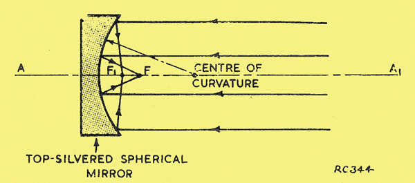
Figure 2
Spherical aberration is most easily understood from Fig. 2, where it will be noted that rays far from the axis A-A1 come to a focus at F1, and rays near the axis at a focus F which is situated from the mirror surface at a distance of one half of the radius of curvature of the said surface. The correction of spherical aberration was solved by B Schmidt, an instrument maker of the Hamburg Observatory at Bergedorf, who perfected his system (known as the Schmidt system) in 1931. Schmidt, however, was mainly interested in telescope optics.
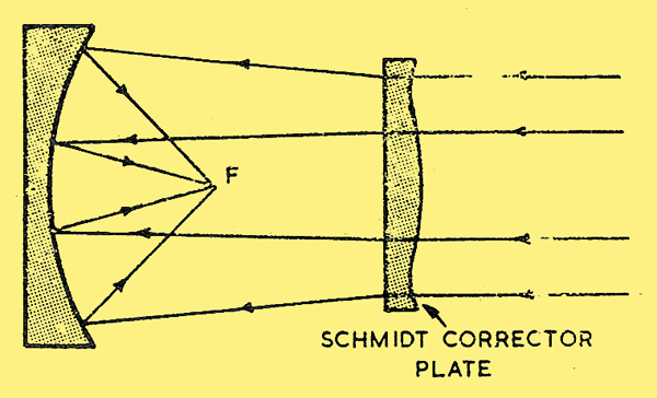
Figure 3
To understand the way in which the Schmidt corrector plate eliminates spherical aberration, consider Fig. 3. The corrector plate is aspherical, and its contour is much exaggerated for ease of description. It will be seen that the corrector plate makes marginal rays diverge, and rays near the axis converge, before they impinge upon the mirror surface. The image surface, however, is spherical, concentric with the mirror surface, and situated at a distance of about half the radius of curvature.
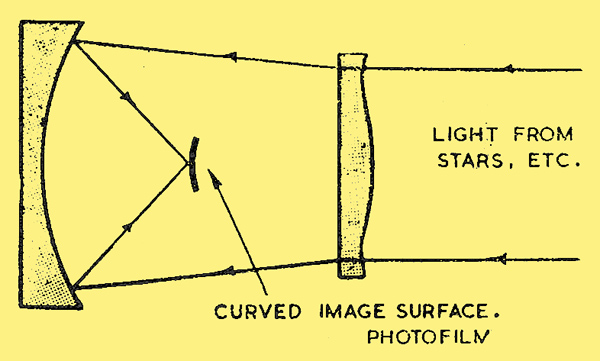
Figure 4
This is the system of optical enlargement which is now favoured in projection television. While the system was invented for astronomical research, where the light from the stars and planets comes in to the system as shown in Fig. 4, the reverse is the case in the television application, Fig. 5.
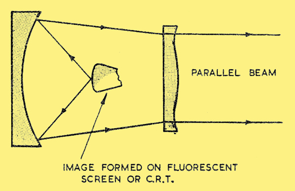
Figure 5
In the astronomical application, the incoming light is brought to an image on a photographic plate (Fig. 4) which is bent to a curve in conformity with the mirror surface; this, incidentally, is a minor objection of the telescopic Schmidt camera.
In the television application this objection is not valid for the manufacture of the cathode ray tube with a curved screen is not a difficult matter.
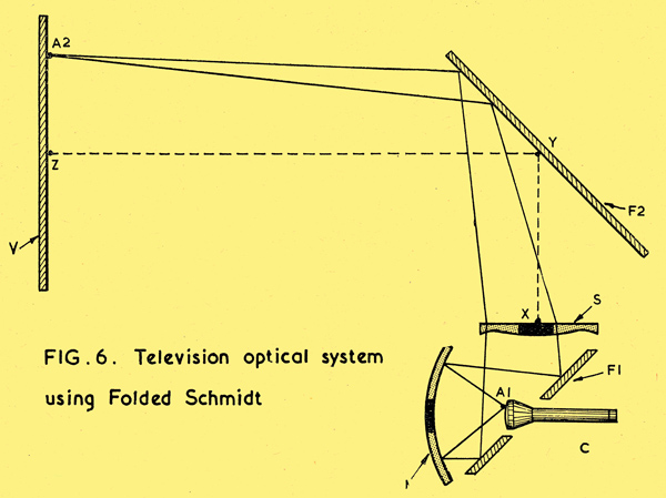
Figure 6
I am indebted to Mullard Ltd. for permission to disclose the Schmidt system which they have utilised for their fine projection television receivers, Fig. 6. This system is a folded Schmidt system, and the direction of the light path will be obvious from the diagram. The components of Fig. 7 represent the basic three units of the Mullard system (a) the MW6-2 2.5 inch cathode ray tube, (b) the optical system, and (c) the EHT unit.
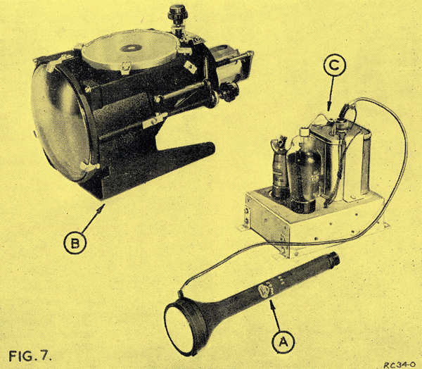
Figure 7
(a) The Mullard cathode ray tube is the type MW6-2, having a face diameter of 2.5 inch. The size of raster employed is about 1.25 x 1.75 inches so that, to obtain a picture giving good definition, the spot size must be between 1/300 and 1/400 of an inch. An EHT potential of 25 kV and an average beam current of 100 to 200 μA are employed. Peak beam current is of the order of 800 μA. The face of the tube is spherically curved, and the screen is metal backed (aluminium), which permits easy penetration by the electron beam and is also a good optical reflector. The screens primary function is to reflect outwards a large proportion of the emitted light which would otherwise be directed towards the rear of the tube. The increase in forward-going light is claimed to be 75-80 per cent. The metal backing also reduces the risk of ion burn, as the negative ions are not able to pass through the aluminium film.
(b) The optical unit is available in five models, giving pictures of 15.5, 17.75 or 19.875 inches diagonal for cabinet viewing, or 44 or 52 inches for wall projection. The magnification of the 2.5 inch picture requires a throw of 25 to 32 inches for the various cabinet viewing models. In order to accommodate such throw distances in a cabinet of reasonable size, the light path is folded as already shown in Fig. 6. The optical principle of the enlarger is basically as follows: A single picture element A1 (Fig. 6) on the curved screen of the tube C impinges on the spherical mirror M, and is reflected as a convergent beam on to the flat mirror F1 tilted at 45° and provided with an aperture for the tube C. The light is now reflected through the Schmidt corrector plate S, where it is corrected for spherical aberration to give sharpness of focus at the throw distance XYZ. The light is now reflected from the mirror F2 and projected toward the viewing screen V at point A2. Similarly, magnified images of all other picture elements are formed in succession on the screen V.
(c) The EHT supply uses the pulsed oscillator system, and while a description of this interesting unit is outside the scope of this article the reader is directed to Mullard Outlook Vol. 2 No. 7 of April 1952 and other sources [4] Projection Television Receivers. Parts 1, 2, 3, 4 and 5. Philips Tech. Review. Vol. 10 1948/49, pp.69, 97, 125, 307, 364, also p.286. [5] Prisms and Lens Making. Twyman. Pub. Hilger and Watts, 1952. Optical Instruments. Proc. of London Conference, 1950. [6] Manufacture of Correction Plates for Schmidt Optical System. Philips Tech. Review. Vol. 9, No. 12, 1947, p.349. [7] Testing Wide Angle Mirrors. H W Cox. Journal British Astronomical Association, Vol. 56, p.111..
In conclusion, it will be appreciated that Schmidt, in applying his mind to the problem and solution of fast, wide-angle astronomical cameras has gratuitously provided television with an exceptionally fine optical system which manufacturers are now exploiting to the full. It is notoriously difficult to predict trends in electronic design, but many are of opinion that projection television with its good definition and other advantages may eventually become the orthodox television receiver.
Readers interested in the Schmidt optical system per se are recommended to consult the works listed under reference [8] B Schmidt. Mitt. Hamb. Sternwarte in Bergedorf. 7, No. 36, 1932..
References
- Enlarged Projection of Television Pictures. M Wolf. Philips Tech. Review, Vol. 2 1937, p.249.
- The Five Aberrations of Lens Systems. A E Conrady. Monthly Not. Roy. Astron. Soc. 79. 60-66. 1918.
- Optical Aberrations in Lens and Mirror Systems. W de Groot. Philips Tech. Review. Vol. 9, 1947/48, p.301.
- Projection Television Receivers. Parts 1, 2, 3, 4 and 5. Philips Tech. Review. Vol. 10 1948/49, pp.69, 97, 125, 307, 364, also p.286.
- Prisms and Lens Making. Twyman. Pub. Hilger and Watts, 1952. Optical Instruments. Proc. of London Conference, 1950.
- Manufacture of Correction Plates for Schmidt Optical System. Philips Tech. Review. Vol. 9, No. 12, 1947, p.349.
- Testing Wide Angle Mirrors. H W Cox. Journal British Astronomical Association, Vol. 56, p.111.
- B Schmidt. Mitt. Hamb. Sternwarte in Bergedorf. 7, No. 36, 1932.
The invention of television greatly impacted American society and culture. TV dinners became popular in the 1950s so families could enjoy a turkey or meatloaf dinner while watching their favorite TV shows. Moms no longer needed to know how to cook meatloaf from scratch once meatloaf TV dinners came on the scene.
|