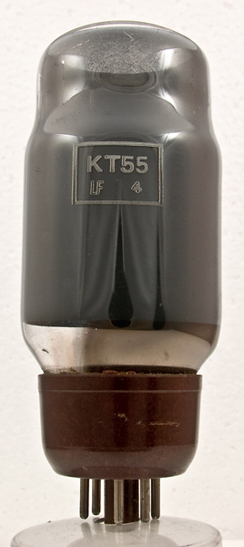
The KT55 is a post-war low HT variant of the KT66 designed for universal (AC/DC) equipment where the absence of an HT transformer would limit the HT available to 200 to 230 Volts and employ a half wave rectifier. The heater is a 300 mA type and to deal with the low HT and thus corresponding greater HT current requirement generates greater heat than the KT66. Cooling of the envelope is therefore often required. In fact the KT66 has an 8 Watt heater and the KT55 consumes 15.6 Watts.
The PDF data sheet for the KT55 contains a circuit supplement including a 25 Watt Ultra Linear Audio Amplifier. This circuit operates direct from the mains without a mains transformer. Unlike a radio or television without external connections an amplifier is by definition designed to connect to an external signal source. If wired incorrectly the chassis, and all connected equipment, would be at live mains potential and thus potentially lethal. In the early days of amplified popular music there were occasional reports of musicians electrocuted on stage or whilst practicing. Thus for health and safety reasons this type of equipment must not be used today unless connected through a one-to-one isolating transformer with the chassis earthed. In practice the cost and weight of the isolating transformer would make this low HT amplifier obsolete.
With the large heating requirement of a pair of these valves it would be unlikely that they would be a valve of choice for new equipment.
The KT55 is also rated for series pass duty in stabilised power supplies and inverters.
The maximum anode voltage is 400 but the design examples are for use with an anode voltage of 200 to 225 as one would find in equipment where the HT is rectified mains.
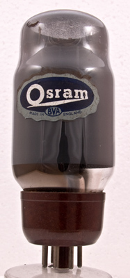
The Osram label but the electrodes are obscured all the way round.
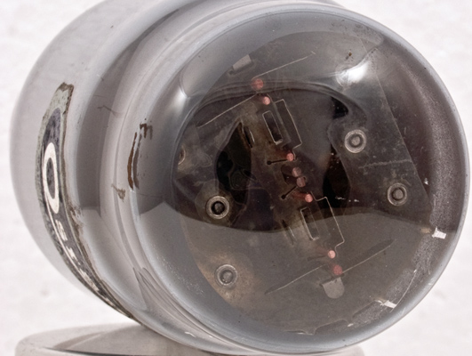
Looking into the dome one can see the top mica and the tops of the electrodes. There are two cathodes, two sets of control grids with heat sink fins attached and two sets of screen grid supports. The beam confining plates are a single set placed outside the screen grid outer rods. The reason for the high heater Wattage now becomes clear, to achieve the high current low voltage performance needs twice the cathode area.
The classic envelope is 51 mm in diameter and, excluding the IO base pins, is 114 mm tall.
Reference: Data-sheet. Type KT55 was first introduced in 1955. See also1955 adverts.