|
RG1-240ASensibly equivalent¶ to:See also:
|
|
|
|
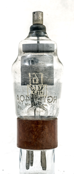
The RG1-240A (CV1072) is a high voltage half wave rectifier. To deliver DC power to medium sized equipment, several would be operated together. Maybe six on a three phase supply.Mercury vapour rectifiers of the GU1 class were introduced in the mid-1930s but, despite filling a real need, they became unpopular because they were troublesome in service. The RG1-240 was introduced in 1938 and the A variant some time later.It took valve designers an amazingly long time to learn that the oxide-coated filament had to be shielded from the anode, that the anode-shield gap needed to be uniform and smoothly profiled, and that use of a thermal delay switch (e.g. DLS10) was essential. The RG1-240A is a later rectifier exemplifying these features. It was successful and widely used. Exhibit NU8 (equal to RG1-125) exemplifies an earlier, much less successful design which the Navy nevertheless went on using for years.The maximum reservoir capacitor had to be limited to 5 µF.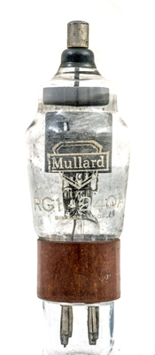
The Mullard commercial RG1-240A designation is on the opposite side to the CV1072 overprint. The mercury has condensed on the inside of the glass.The classic envelope is 45 mm in diameter and, excluding the B4 base pins, is 115 mm tall.References: Data-sheet, 1040 & 1043. Type RG1-240A was first introduced in 1938. See also 1938 adverts. |
Pin Connections
| 1 | 2 | 3 | 4 |  nc | nc | f | f |
|
|
Absolute Maximum Operating Conditions
| Vh | Ah | Va | mAa | 
| 4.0 | 2.7 | 2,220 | 250 |
|
PDF scanned from an original document held by the museum |
Updated March 07, 2024.
|
|