|
In the writer's experience, so many people have trouble when using EF50 valves that it was felt an article on the subject would be of some assistance to readers.
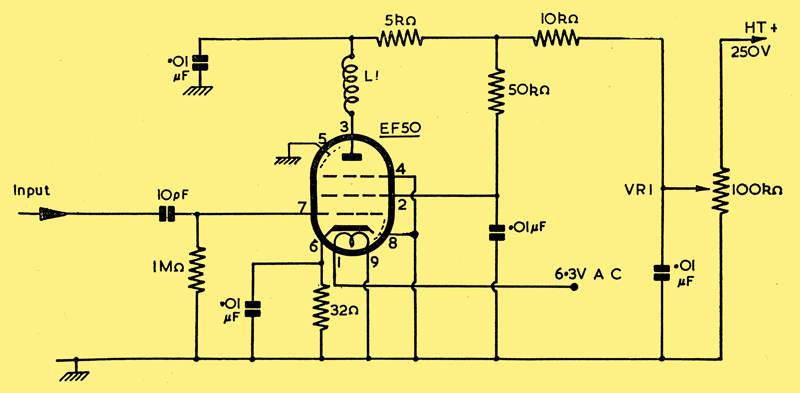
General purpose IF or RF amplifier
These troubles, it seems, fall into three separate classes, (1) Very high noise level sufficient to swamp weak signals. (2) Severe instability with uncontrollable oscillation tendencies. (3) Complete lack of, or very little, gain.
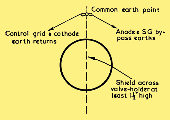
If we take these faults and analyse them, we shall find that in all cases the valves are being operated incorrectly in one form or another. The EF50 is a high gain valve and is naturally more critical as regards its operating conditions than a more docile valve, such as the 6J7 for example. Keeping this in mind, it is obvious that any form of coupling between anode and grid will result in severe instability. Screening must be such that anode and screen grid pins and connections must be completely shielded from the control grid, cathode pins and connections, and all returns for the valve returned to one common point. This is very important, and includes the earthy end of the grid circuit.
A method of doing this is shown below; note that the screen is also shielding the earthing wires.
Still remembering the words 'high gain', let us consider the input. The valve operates with a negative bias of -2V. No input signal must exceed this figure, or the valve will be over-driven and distort badly or give very weak signals, usually both. The input circuit must therefore be chosen to prevent over-driving, and a gain control provided to reduce amplification of the early stages of the receiver. The circuit shown has been fully tested by the writer and will enable an EF50 to be operated at full gain.
It is impossible to use all the gain available from two EF50s in cascade on an average signal input. The only reason for using two such valves is to give extra selectivity, and where two are used as an IF amplifier, the first valve is always controlled as is shown in the main diagram above.
The coil L1 can be the primary of an IF transformer or the anode winding of an RF coupling coil. The input can be the secondary of an IF transformer or a tuned grid coil for RF. AGC can be applied to this circuit, but is not recommended with the values shown. This arrangement will work well between 400 kHz and 40 MHz, but for higher frequencies it may be wise to use small capacitors (say 50pF) in parallel with the 0.01pF values.
A superhet using this circuit with one RF, Mixer, Oscillator, and two stages of IF, is always operated with VR1 on the first IF stage, this control being set at its minimum value (10 Volts on the valve). If this is not done, the following stages will be over-driven, especially when receiving CW signals with the AGC set in the off position.
The last point to be covered, number one in our list, is the high noise level question. The answer is very simple, high gain is being used in an attempt to compensate for low Q tuning circuits, which is seldom satisfactory. In addition to the foregoing, any noise caused by faulty soldered joints or aerial/earth connections, is amplified more with a high gain valve.
An EF50, used as an RF amplifier in front of an average receiver, will give surprising results - quite capable of overloading the receiver.
|