Initially the U14 and the U12 were the same valve intended to meet all HT requirements up to a maximum of 120 mA at 500V, using a capacitor-input filter. However, some valves performed better than others on final factory test so the best ones were graded and marked U14 whilst the also-rans were marked U12.
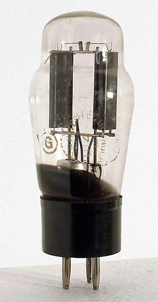
This exhibit is of later (1940s) manufacture, note that the anode is made of sheet rather than gauze, indicating greater confidence in the quality of vacuum. The photograph shows that the valve is marked with a white G in a circle. This means that it is from a production batch originally ordered by the Ministry of Supply during WWII but which remained unused and therefore surplus when the War ended. Such 'G' valves were returned to their manufacturers at a nominal price so that they could be re-marked with civilian type numbers and exploited in the civil market. Supposedly to boost the export capability of war-weary British Industry.
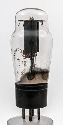
Another example of the U14 with the etched M-OV lozenge clearly visible.
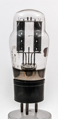
The anodes of this example are stitched along the seam length.
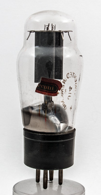
The remains of the Marconi paper label.
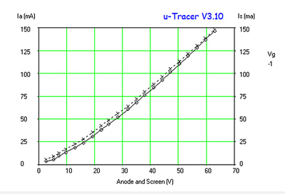
The graph shows the voltage drop across the valve shown above plotted against anode current. The legend actually refers to the two anodes.
This U14 was designed to work with a maximum reservoir capacitor of 32 µF and to have an effective series resistance of 100 Ohms. The filament is a thin inverted V ribbon in each of the two anode cavities.
The classic envelope is 44 mm in diameter and, excluding the B4 base pins, is 102 mm tall.
References: Data-sheet & private communication. Type U14 was first introduced in 1931. See also1931 adverts.