|
Effective amplification at Ultra-Short wavelengths. This article explains why the recently introduced miniature valves known as Acorns can be operated effectively at wavelengths much lower than is possible with ordinary types; methods of using the valves to the best advantage are also discussed.
It is often left to be supposed, or it is even actually stated, that the secret of the efficiency of the Acorn type of valve at ultra-high frequencies is its low inter-electrode capacity. It is true that a reduction in capacity is helpful, but if the facts are considered there is no difficulty in seeing that this explanation of the Acornbs superiority is not the most important one.
Compared with the midget type of valve, the inter-electrode capacities are less by only about 1 pF. But effective amplification is possible with the Acorn at something like five times the frequency. Even when compared with standard full-size types of valve, the extension in performance is out of proportion to the reduction in capacities. And the important anode-to-grid capacity that is usually the limiting factor in RF amplification by screen-grid tetrode or pentode types of valve is no smaller in the Acorn than in most other kinds.
The less obvious, but more important, factor in the matter is a serious form of loss that exists when the time taken by the electrons to cross the space inside the valve is not negligible compared with the time of one complete oscillation. At a frequency of 100 MHz (wavelength of 3 metres) the time occupied by one oscillation is, of course, one hundred- millionth of a second; and for a valve to work effectively it must be designed so that the transit time is a very small fraction even of this brief moment. In ordinary valves this condition is not fulfilled; and, while one would expect as a result some interference with the regular mode of operation, it is certainly not obvious that it has the effect of reducing the input resistance of the valve - ordinarily of the order of a megohm to a few thousand Ohms.
The connection between this effect and its cause is explained in a recent article, [★] Grid Loss at Ultra-High Frequencies, The Wireless World, October 23rd, 1936. See extra menu. which also gives the results of some measurements made on valves at ultra-high frequencies. The sort of result one gets at, say, 60 MHz (5 metres) is 5,000 Ω for the input resistance of an ordinary valve and 25,000 Ω for an Acorn. At the former figure a tuned input circuit is to a large extent short-circuited; at the latter a very useful amplification is possible.
Centimetre Wavelengths
As a matter of fact, amplification at a frequency as high, as 430 MHz (0.7 metre) is claimed for the Acorn. When the input resistance of a valve, expressed as a conductance, is equal to mutual conductance no amplification is possible, even theoretically. Thus, if the mutual conductance of the valve is 1.25 mA/V, equivalent to 800 Ω resistance, there is no use attempting to amplify if the input resistance is no greater. In practice, in order to allow for circuit and other losses, a considerably higher figure is necessary.
The point to notice about this is that there would be no advantage in raising the input resistance of a valve if at the same time the mutual conductance were dropped in similar proportion. Fortunately the reduction in electrode spacing necessary to achieve the former object tends to produce a better mutual conductance; or at any rate to offset the loss that would otherwise be caused by reducing the surface areas of the electrodes.
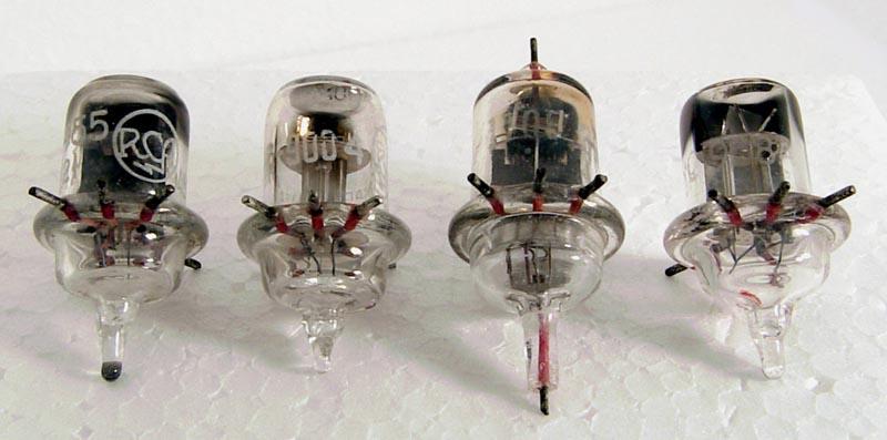
The race for higher and higher valve conductances has already brought the spacing of electrodes as close as is at all practicable for mass production; the still smaller clearances necessary to achieve the performance of the Acorns necessitate very delicate hand construction, and correspondingly high cost. The complete cathode, with insulated hairpin heater inside, is no thicker than an ordinary pin; and the clearances between electrodes are as little as a two-hundredth of an inch. So, although their small dimensions and lively all-round characteristics render Acorns attractive for many purposes, economic reasons confine them to applications where no others will do-namely, ultra-high-frequency work.
Those listed at the moment include the Mullard AP4 pentode, which, except for the 4-Volt heater, is similar in rating-to the RCA 954 (imported by Messrs. Claude Lyons). Triodes are made by Mullard (AT4), RCA (955), and Osram (HA1). Mazda produces two types: the A40 triode and the A41 pentode.
Elsewhere in this issue [★] Not reproduced here are given tabulated characteristics which, it will be seen, are in most respects comparable with those of any ordinary valves of corresponding type; in fact, except for the somewhat lower inter-electrode capacities, it is difficult to discern anything special about them. All are indirectly heated, but need not for this reason be considered for mains drive exclusively; the heater current ratings are from 0.15 to 0.3 Amps, which makes no excessive demand on even a small accumulator.
The Acorn pentode is capable of giving an amplification of at least 3 at a wavelength of one metre. For signals in the television Waveband -for example, for a stage of amplification ahead of the frequency-changer - a considerably larger gain is possible, whereas with ordinary valves it requires very careful design and arrangement to get any amplification at all.
To derive the full benefit of the Acorn construction one must, of course, arrange the circuits to suit. Special holders are obtainable, made of low-loss ceramic material and designed to avoid unnecessarily prolonging the leads to the valve. Incidentally, the makers warn users of the valves not to attempt to minimise the length of leads by soldering them direct to the valve contact wires, as this would probably crack the glass and destroy the vacuum.
By-pass capacitors for ultra-high-frequency circuits ought to be good in the electrical sense, and connected as close up to the valve and oscillatory components as possible. One way of doing this is to mount the apparatus on a thick sheet of copper, which forms the earth and one side of all by-pass capacitors, as illustrated in Fig. 1.
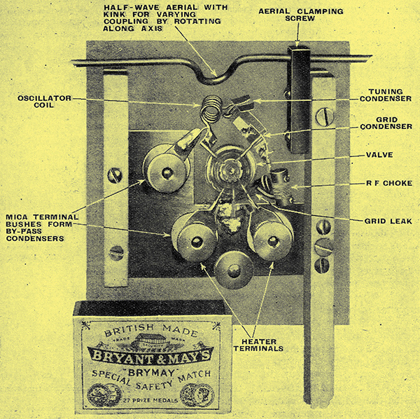
Fig. 1. - Arrangement of ultra-high-frequency transmitter employing Acorn triode. Note metal base forming one plate of all by-pass capacitors.
In a Wireless World article some years ago [★] By-Pass Condensers for 5-Metre Work, The Wireless World, September 29th, 1933. I showed that there is no point in making by-pass capacitors too large; in fact for each frequency there is an optimum capacity which just balances the inductance of the connecting leads and of the capacitor itself, thus giving a lower impedance even than an infinitely large capacitor.
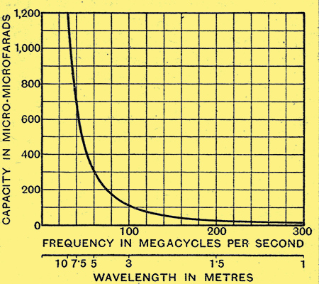
Fig. 2. - Optimum capacity of by-pass capacitors, assuming that the total length of connections (including the capacitor electrodes themselves) is about one inch.
On the assumption that the inductance within and without the capacitor is equal to that of one inch of straight wire, the graph (Fig. 2) gives the optimum capacitor capacity for any frequency in the ultra-high band. In any particular case the inductance may differ considerably from that assumed, but when the connections have been reduced to a minimum the graph is a useful guide to the order of magnitude of capacity needed. It is advisable to select the capacity on the basis of the lowest frequency at which the circuit is to work. Too much capacity is better than too little.
The RF parts of the circuit may be isolated by chokes. For not more than a few metres, 15 turns of 30 DSC wire on a ¼ in. ebonite or glass tube is suitable.
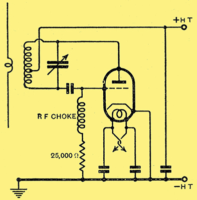
Fig. 3. - Circuit diagram of oscillator shown in Fig. 1.
The circuits themselves may be more or less standard, as Fig. 3 exemplifies. This is the circuit diagram corresponding to Fig. 1, which is a picture of a low-power transmitter working on a wavelength of 80 cms. It can readily be seen that it does not make extensive demands on space. I hope to be able to give some account of this transmitter and the corresponding receiver, and the results obtained therewith, in a subsequent article.
For Miniature Transmitters
It will be recalled that for a stunt by the NBC in America a miniature transmitter embodying an Acorn was mounted, complete with half-wave aerial, on the top hat of the announcer, who interviewed passers-by on the street and radiated their remarks so that they could be relayed by the broadcasting stations.
In oscillator circuits the Acorn triode functions right up to about 750 MHz (0.4 metre). Since a half-wave aerial, or dipole, for this frequency is only 8 in long, the scope for miniature transmitters with good radiating properties is clear. The power output above 300 MHz is small, but is effective for communication over several miles so long as intervening obstructions do not cause excessive screening. At 60 MHz (5 metres) the output in a Class C (over-biased) oscillator circuit may be as much as half a Watt, with an input of 8 mA at 180 Volts.
Naturally, an Acorn triode can be used in a conventional reaction receiver circuit; but it is extraordinarily difficult to find any particular signal, and having found it to keep it. A super regenerative circuit gives enormously greater sensitivity and much less critical tuning; the higher the frequency the easier it is to operate, and it is the obvious system to use for reception at extremely high frequencies.
At the lower frequencies, such as the television and 5- and 10-metre amateur bands, substantial amplification is obtainable with the Acorn pentode. It should be mounted in a circular opening in a metal baseplate or screen, so as to separate the input and output sides of the stage of amplification in the manner of the early SG valve amplifiers.
Although there is not much published information on the subject, there seems to be no reason why the Acorn pentode should, not be advantageously used as a mixer valve in conjunction with a separate oscillator in a superhet. For television frequencies the benefit of higher input impedance might not be worth the much greater valve cost, but at the very highest frequencies it is difficult to see what other valve could be used for the purpose.
A useful application, not only at very high frequencies, is in a valve voltmeter. By mounting the valve at the end of a flexible metal tube it can be brought right up to the work, and the input impedance is much higher than usual.
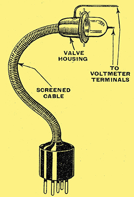
Fig. 4. - How a valve voltmeter can be brought right to the job. The extreme shortness of live connections makes it very suitable for ultra-high-frequency work.
Fig. 4 shows the general idea, and Fig. 5 is a circuit recommended by the RCA. The 954 pentode with the electrodes connected to give a triode is specified, presumably to take advantage of the convenient grid spike, but, of course, the 955 triode or its equivalent can be used for the purpose, and is to be preferred as being a more reliable valve.
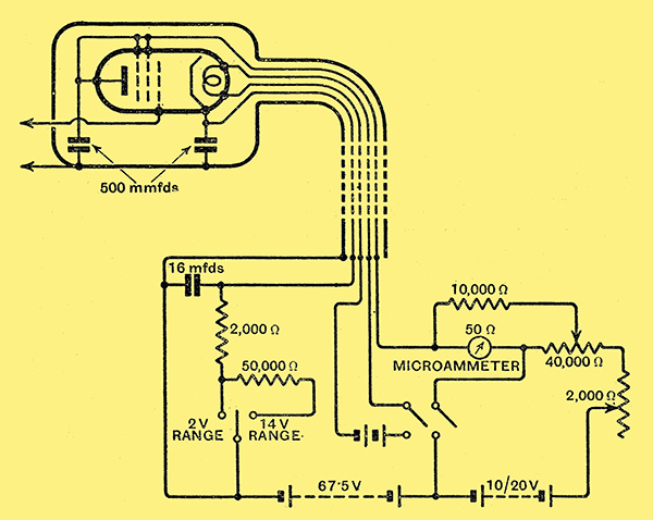
Fig. 5. - Circuit of valve voltmeter, due to Radio Corporation of America.
|