|
The various applications of the miniature Acorn valves, which have been designed especially for use on the ultra-high frequencies, and the circuits found most suitable for them, are discussed in this article by a member of the Technical staff of the M-OV company.
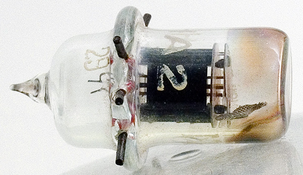
M-OV Acorn Triode Type HA2.
At frequencies above 50 MHz it has been found that the amplification obtainable from normal receiving type valves decreases rapidly, which is due in part to the time of flight of the electrons from the cathode to the various other electrodes being comparable to one cycle of the frequency of operation and in part to the high self-capacity and inductance of the valves.
The only satisfactory method of obtaining a reasonable stage gain at frequencies between 50 and 300 MHz is by means of the Acorn valve.
These valves, which are now available both as triodes and as screen pentodes, have such a small physical size that their inter-electrode capacities are very low. Their small physical size also reduces the time of flight (electron transit time) until it is no longer troublesome, and the short leads to the elements permit the inductance of the circuit to be concentrated mainly in the tuning coil.
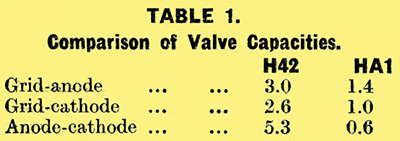
In Table 1 the respective capacities of a mains triode, the Marconi or Osram, H42, and the Acorn triode of this make are given for comparison purposes. It is interesting to note that the output, or anode-cathode capacity, of the Acorn is relatively very much smaller than the other capacities.
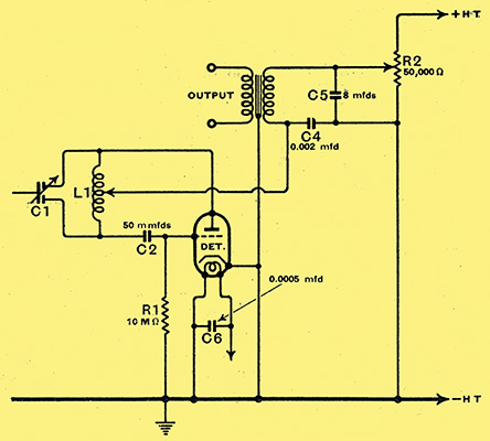
Fig. 1. Circuit for an Acorn triode used as an ultra-short wave regenerative grid detector.
The triode valve will be considered first as it is the simpler type, and, being cheaper, is more likely to be popular at the present time. Its first and most obvious use is as a regenerative grid detector, to which super-regeneration may be added if desired. The circuit recommended is shown in Fig. 1, which as will be seen is similar to the well-known Hartley oscillator circuit, but regeneration is controlled by varying the anode voltage by means of the resistance R2. Increasing the anode voltage beyond the oscillation point causes super-regeneration to start, the frequency of which is partly determined by the grid leak and capacitor R1, C2. This gives a smooth control and does not disturb the tuning of the circuit.
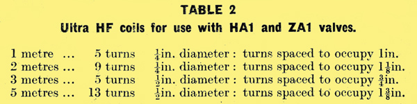
All coils are wound with 16 SWG copper wire and the tuning capacitor is that shown in Fig. 2.
The size of the coils and number of turns required for various wave-lengths are given in Table 2. The tapping on the coils should be near the centre, but the position for best operation will have to be found by experiment, since at very high frequencies the layout of the components, wiring, etc., greatly influence the operation of the circuit.
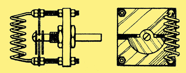
Fig. 2.Details of split-stator condenser recommended for ultra-short-wave sets and showing also method of mounting the coil.
A tuning capacitor having a very low inductance is essential at the ultra-high frequencies, and the one used in the original experiments with the valves was made as shown in Fig. 2. Its construction provides a convenient way of mounting the coil.
It is a differential-type capacitor, and connection is made to the two fixed vanes only, the rotor merely serving to vary the capacity. As no connection is made to the rotor, perfectly silent operation is ensured. In this capacitor the rotor plates are semi-circular and have a radius of ⅝ in., which dimension will give a good indication of the size of the other parts required.
This capacitor was used for the very high frequencies, but at 60 MHz or so more plates, or even a larger capacitor of standard pattern, can be employed. The use of the smallest capacity to tune over the waveband to be covered is most desirable, as it enables the largest possible inductance to be employed.
Receiver Assembly
The mechanical layout of this circuit is very important, and the components must be arranged so that short leads can be made. (The Acorn valve lends itself very well to this, due to the manner in which the leads come out from the side of the glass pinch.
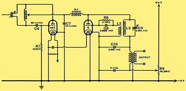
Fig. 3. Super-regenerative circuit using an Acorn triode for the detector valve.
A two-valve circuit employing a separate quenching valve, which gives a higher efficiency than the self-quenching circuit of Fig. 1, is shown in Fig. 3. The quenching valve does not need to be an Acorn, and a valve of the MHL4 class can be used. The coils L2, L3 are a standard quench oscillator unit.
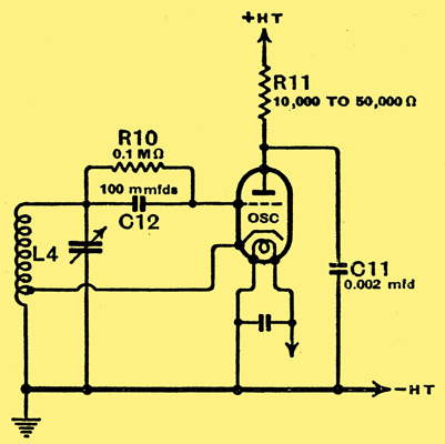
Fig. 4. Typical oscillator circuit using an Acorn triode valve.
The HA1 valve may be used as an oscillator, using the circuit shown in Fig. 4. Used in conjunction with an Acorn pentode, the ZA1, an ultra-high frequency superheterodyne, can be built. The coil L4 can be similar to those given in Table 2, though in the interests of frequency stability 30% fewer turns should be used, together with a larger capacitor; which need not be of the special type previously described. Further details of the ultra-high-frequency receiver will be given when the Acorn pentode is discussed. The cathode tap should include one-quarter to one-half the total number of turns.
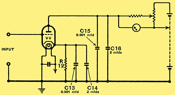
Fig. 5. Using this circuit an Acorn triode can be employed as a valve voltmeter.
The Acorn triode is particularly suitable for use as an anode bend detector for valve voltmeter use, and, due to its high input impedance and small physical size, very little extra loading is put on the circuit at frequencies up to 20 MHz. A suitable circuit is given in Fig. 5. The resistance R12 biases the cathode to a Voltage, E + 1 volts, when E is the peak value of the input to the grid. When working at frequencies above 5 MHz, the mica capacitors C13 and C15 are necessary, in addition to the larger paper capacitors C14 and C16. It is suggested that the valve and mica capacitors be mounted in a small shielding can with a flexible lead to the meter and batteries, so that the valve may be placed close to the circuit to be measured.
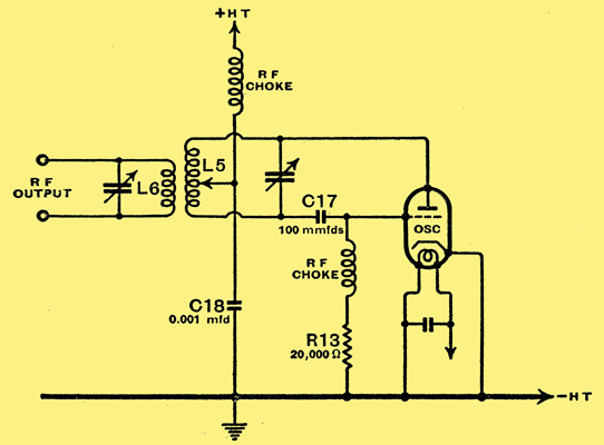
Fig. 6. Circuit for a low-power ultra-short-wave transmitter.
Fig. 6 shows a suitable circuit for a low-powered transmitter. Coils similar to those previously described may be used up to 150 MHz but at higher frequencies the use of parallel or concentric tubes (Fig. 7) is recommended, as much higher efficiency and greater frequency stability is thereby obtained. The position of the tap on coil L5 in Fig. 6 should be varied to produce the greatest output. A small transmitter made with the circuit of Fig. 7 gave good results at 300 MHz i.e., one metre. It is built on a copper chassis which serves as a support for the lines; the anode line is earthed by the capacitor shown, which is formed by interposing a piece of mica between the chassis and the copper support for the line; The length of each parallel line should be about 4 in, and final tuning is done by the capacitor C20.
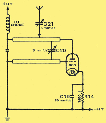
Fig. 7. Good frequency stability at the very high frequencies can be obtained with this circuit used as a transmitter.
The aerial for local work may be a short vertical rod. Even higher efficiencies and greater frequency stability may be obtained by the use of concentric lines, each line being about ¼ wavelength long, and the ratio between the diameters of the outer and inner conductors being three or four to one.
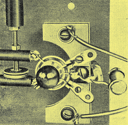
Method adopted for mounting the valve in the 'long-lines' transmitter of Fig. 7. The disc-type variable capacitor is C20 while on the right of the valveholder are C19 and R14.
The Acorn pentode is a development of the triode; it enables real RF amplification to be obtained at frequencies above 50 MHz, where the normal receiving valve is likely to act more as an attenuator than as an amplifier. In appearance the pentode ZA1 is similar to the triode already described, but the anode and control grid connections are brought out at opposite ends of the glass bulb. This allows the valve to be mounted on a metal screen with the grid and anode circuits completely shielded from each other; the connections brought out through the glass pinch should all be maintained, as far as RF is concerned, at earth potential when the valve is acting as an amplifier. A special type of mounting enables this to be done. The by-pass capacitors, which are almost a part of the valve holder, form a very low inductance path from screen to cathode. Where other capacities are required, such as across the cathode bias resistance, further copper and mica discs can be added. At the lower frequencies, between 25 and 50 MHz, where the Acorn valve has still an advantage over the normal pentode, this special type of holder is unnecessary, and small mica capacitors mounted close to the valve give satisfactory results. At still lower frequencies, apart from the small physical size, the Acorn has little advantage over the ordinary type of valve.
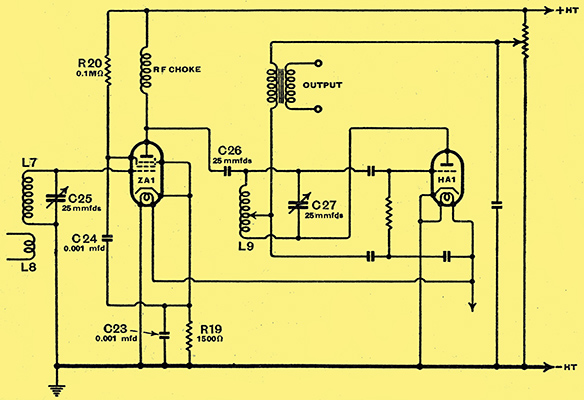
Fig. 8. An Acorn pentode used as an RF amplifier followed by a triode of the some type arranged for ultra-short-wave reception.
Fig. 8 shows a suitable circuit which is similar to that used at the lower frequencies, apart from some of the component values. The ZA1 valve is coupled to a super-regenerative detector similar to that shown in Fig. 1, with considerable improvement in selectivity and reduction in radiation from the oscillating detector. The coils L7 and L9 should be similar to those described in Table 2, but due to the larger capacitors needed to give wider tuning range, about 30% fewer turns should be used. The aerial coil L8 should have about 6 turns of 16 SWG wire wound to ½ in diameter.
Many other types of super-regenerative circuits using these valves could be devised. Suppressor injection of the interruption or 'quench' frequency can be employed, and this method of operation would seem to have several advantages. Independent control of the various voltages is available with this scheme, and although little practical work has been done with this particular arrangement, it is one that is well worth further investigation.
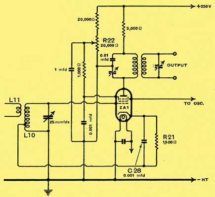
Fig. 9. Frequency changer circuit for UHF reception using an Acorn pentode with RF regeneration and separate oscillator.
As a frequency changer valve in conjunction with a separate oscillator the ZA1 will give good results, using the circuit shown in Fig. 9. To increase the stage gain, regeneration is produced by tapping the cathode into the grid coil, and it is controlled by variation of the screen voltage. If regeneration is not required, the ZA1 cathode may be returned to earth, and a further ZA1, using part of the circuit of Fig. 8, used as an RF amplifier. As before, the coils used for 50-60 MHz work should consist of about 8 to 10 turns of ½ in diameter, the exact frequency coverage being obtained by altering the spacing of the turns i.e., pulling the turns apart reduces the inductance and vice versa. It should be remembered that the usual amplifier using an IF of 460 kHz is hardly suitable for use in an ultra-high-frequency superheterodyne; frequency instability of the transmitter and receiver will be emphasised, and satisfactory reception will be impossible. A high IF of 5 MHz, having a bandwidth of, say, 50 kHz, will obviate this and at the same time enable high fidelity broadcast programmes on the ultra-high frequencies to be received.
Acorn valves are, of course, not required in the IF amplifier but only for the frequency changer, local oscillator and RF stage if one is used.
|