|
A full explanation of the internal screening system of the modern HF valve is followed by a description of its electrical properties, and the natural limitations imposed upon the amount of amplification per stage are discussed.
The problems of high-frequency amplification with the triode give rise to two conclusions. First, that the anode load for a valve used as high-frequency amplifier must almost inevitably be a tuned circuit; and second, that the grid-anode capacity would infallibly result in uncontrolled oscillation unless means were taken to neutralise it by a special circuit. Alternatively, we may try to find a valve in which the capacity between grid and anode has been reduced to negligible proportions.
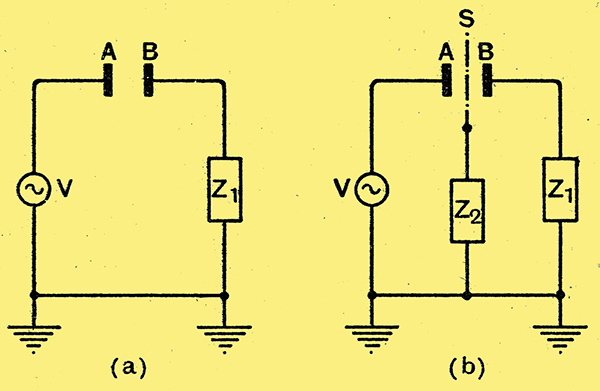
Fig. 1. - Illustrating the theory of screening.
The capacity between any two objects can be reduced to zero by interposing between them as a screen an earthed metal sheet of sufficient size. The operation of such a screen can be understood by considering Fig. 1, which shows at (a) two plates A and B separated from one another by an air-space. There will be a capacity between them, so that the high-frequency generator V will drive a current round the circuit. Earth - V - A - B - Z1 - Earth. Across Z1, which is an impedance of some kind between B and earth, the current will develop a potential difference, and this PD will be the voltage appearing on B as a result of the passage of current through the capacity AB.
At (b) third plate S, larger than the larger of the two original plates, is inserted between them in such a way that no part of either plate can 'see' any part of the other. We now have no direct capacity between A and B, but we have instead two capacities, AS and SB, in series. If an impedance Z2 is connected between S and earth the current round the circuit Earth- V - A - S - Z2 - Earth will develop a PD across Z2. Since Z2 is also included in the right-hand circuit the PD across it will drive a current round the circuit Earth - Z2 - S - B - Z1 - Earth, and this will give rise to a potential on B. So far, S has not screened A from B, there remaining an effective capacity between them which if Z2 is infinity large, amounts to the capacity equivalent to that of AS and SB in series. If S is thin this is practically equal to the original direct capacity between the two plates.
Now imagine Z2 to be short-circuited. Current will still flow round the first circuit, but since there is now no impedance common to both there will be no driving voltage to produce a current in the latter. No matter what alternating voltages are applied to A, none will appear on B; even though large currents may flow via S to earth. The effective capacity between A and B has therefore been reduced to zero, and B is completely screened from A.
It is very important to note that S is only effective as a screen if it entirely cuts off A from B, thus replacing the direct capacity AB by AS and SB in series. Even with this proviso, screening is not complete unless S is definitely connected to earth either by a direct wire or through an impedance Z2, which is negligibly small.
This is the principle used in reducing the grid-anode capacity of a valve. A screen, so designed that it completely protects anode from grid, is interposed between these two electrodes within the bulb, while capacity, between the leads running to grid and anode is avoided by taking the lead for one or other of these electrodes out through the top of the bulb. Clearly, a solid metal screen, while providing irreproachable screening, would cut off the electron flow from cathode to anode; it is therefore necessary to use as screen a close-mesh wire gauze through the openings of which electrons can pass. It is found that this necessary compromise with perfection still leaves a completeness of screening that falls short of that obtainable with an unbroken sheet of metal by a surprisingly small amount. In an unscreened valve, Cga is usually of the order of 6 to 8 pF; with a gauze screen, properly earthed, this is commonly reduced to less than 0.003 pF, and may elven be less than 0.001 pF. The structure of a typical screened valve is shown in the sketch,of Fig. 2.
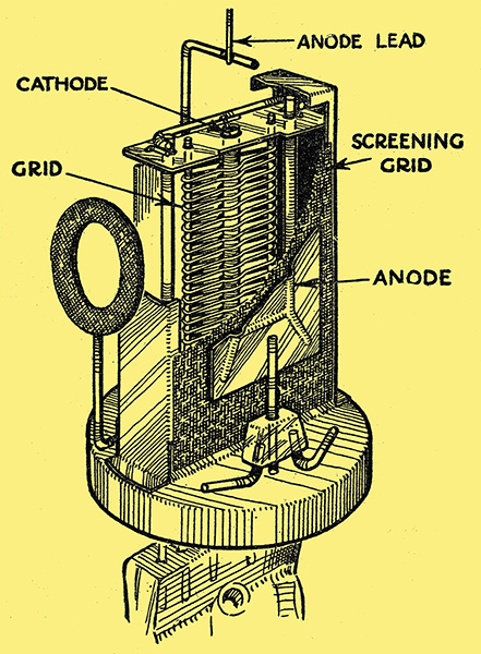
Fig. 2. - Showing construction of a typical screened valve. Note the skirt screening the grid lead (below) from the anode. This skirt is connected to the screen.
If earthed in the strictly literal sense the potential of the screen would be approximately that of the cathode. Since the attraction of the positive anode cannot extend through the screen to any appreciable extent, electrons in the neighbourhood of the grid of the valve would then not be drawn onwards, and the anode current would fall practically to zero. But since, as Fig. 1 shows, the requirements of screening can be met by making, Z2 negligibly small, we can connect a capacitor of large capacity from the screen of the valve to earth, after which we can supply the screen, from any convenient source, with a positive potential.
The inner portion of the valve, comprising cathode, grid, and screen, is practically unaffected by the voltage at the anode; in consequence the total current through the valve is almost completely determined by the potentials of grid and screen. But if an electron arriving at the screen should happen to find itself exactly opposite to one of the openings in the latter, the attraction exerted upon it by the screen will come equally from all sides and, it will go straight through the opening. With the anode at zero potential it would fall back again to the screen, but it the anode is much more positive than the screen it will be drawn on.
Thus by making the anode more positive than the screen some of the electrons, initially set in motion by the positive potential on the screen, will pass through the latter and travel on to the anode. The more the potential of the anode exceeds that of the screen the more electrons will be drawn on; with rising anode voltage, therefore, the anode current rises and the screen current falls, the total remaining practically constant.
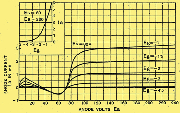
Fig. 3. - Characteristic curves of typical screened tetrode. Only the flat part of the curves to the right of the line Es are used for amplification. Inset: Ia - Eg curve to show approximate constancy, of slope.
High AC Resistance
Due to the peculiar shape [★] Due to secondary emission see Electrons in right menu. -ed. of the curves for values of Ea lower than Es a screen~grid valve is always used with an anode voltage considerably in excess of that on the screen.
The extreme flatness of the curves over the working region to the right of the diagram indicates that the AC resistance of the valve is very high. For the curve Eg = -2, the change of Ia by 0.025 mA. for a change in of 80 V. indicates a resistance of 80/0.000025 = 3.2 MΩ. But this value depends far more than in the case of the triode, upon operating voltages. Reducing the bias reduces also the AC resistance; reading off values from the curve for Eg = -1 gives an, AC resistance of 350,000 Ω only, which is about one-tenth of the value found for Eg = -2.
This rapid variation of AC resistance is not accompanied by corresponding changes in mutual conductance or slope. Reference to the small curve inset on Fig. 3, which shows the variation of anode current with grid voltage at Es = 80 and Ea 200 at once makes clear that over a wide range the slope g of the valve is nearly constant at about 2.1 mA. per volt. At E = -1, g = 2.45, while at E = -2, g = 1.45 mA/V. Since the amplification factor of, the valve is given by μ = g Ro, we can find its value from the figures for g and Ro at these two bias points; at Eg = -2, μ = 1.45 × 3,200 = 4,650, while at Eg = -1, μ = 2.45 × 350 = 880.
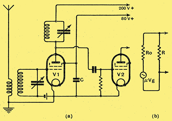
Fig. 4. - A simple HF stage employing a screened valve with tuned-anode coupling, and (dia. b) equivalent anode circuit of the valve. If R is small compared with Ro, gain of stage is approximately gR.
In the triode, the amplification factor is determined almost entirely by the geometry of the valve, and therefore does not vary over these extraordinary ranges; further, it is much lower, seldom exceeding 100. Nevertheless, the screen-grid valve, used as a high-frequency amplifier, does not give such enormously enhanced gain as these startlingly high figures might suggest, for their effect is very largely offset by the valve's very high AC resistance. Fig. 4 (a) shows a simple tuned-anode stage of high-frequency amplification, preceding a grid-detecting triode V2; with the exception of the addition of the screen circuit, with its large by-pass capacitor to earth, the arrangement exactly duplicates that for a triode. At (b) is shown the equivalent anode circuit of the valve, the signal-voltages Vg at the grid being represented, as before, by μ Vg Volts in series with the AC resistance of the valve. If R, the dynamic resistance of the tuned circuit, is 100,000 Ω, the amplification given by the valve works out as 196 times for Eg = -1 and 141 times for Eg = -2. The rising amplification factor has been accompanied by so large a rise in AC resistance that the gain actually drops in passing from Eg = -1 to Eg = -2
In most practical cases the impedance of the valve is so very much higher than that of the tuned circuit connected to its anode that R is almost negligible compared with Ro. A good approximation to the correct value for the stage-gain can then be had by writing A = (μR)/Ro or A = gR. The conditions for high gain with a screen grid valve are therefore simply that we choose a valve of high slope and follow it with a tuned circuit of high dynamic resistance.
Apart from these considerations, the screen grid valve behaves exactly like a triode from which the grid-anode capacity has been removed.
The introduction of the screening makes it quite possible to build up and use successfully a circuit such as that of Fig. 4 without running into difficulties due to oscillation. It can be shown [★] The Stability of the Tuned-Grid Tuned-Plate HF Amplifier, Beatty, Wireless Engineer, January, 1928, p.3. that the stage will be stable provided that the numerical value of a quantity H is less than 2. This quantity is given by the relation H = gωCag R1R2. Where ω = 2π × frequency of the signal being amplified, and R1 and R2 are the effective dynamic resistances of the tuned circuits connected to grid and anode. High values of R1 and R2, which imply circuits of low inherent losses, tend, as might be expected, to produce oscillation. So also do high values of valve-slope or grid-anode capacity, while the likelihood of instability is greater, other things being equal, the higher the frequency of the signal it is desired to amplify.
For a valve for which g = 2.5 mA/V, Cag = 0.005 pF, used at 1,500 Hz (200 metres), we can find now the maximum dynamic resistance that the tuned circuits can have without causing oscillation. For critical oscillation H = 2, so that we can write R1R2 = 2/gω Cag = 2/118 × 1012. If the two tuned circuits are alike each may have a maximum dynamic resistance equal to the square root of this; i.e. of 130,000 Ω. Since this represents a tuned circuit only a little better than the average, it is clear that the inter-electrode capacity assumed for the valve is just on the maximum permissible limit for a single stage of amplification. Even slight coupling between grid and anode leads external to the valve itself would add capacity enough to provoke oscillation; for example, the tuning capacitors, and their leads will need screening.
|
