|
The purpose of every electrode.
Part 1
Progress in valve design has been so rapid during the last year or two that there is some excuse for those who have failed to keep au fait with developments in this all-important branch of radio technique. This series of clearly written articles presents a golden opportunity to make good the omission.
The Triode and the Simple Tetrode
The simplest thermionic valve that can be used to provide amplification of alternating voltages is the triode. As its name implies, the triode contains three electrodes. Of these, one, the cathode, acts as a source of free electrons, which boil off from it into the surrounding vacuum when its specially prepared surface is heated to the requisite temperature.
These electrons, being negative charges, are violently attracted towards the anode, an electrode maintained by a battery, or its equivalent, at a potential considerably more positive than that of the cathode. The third electrode, or grid, is an open-work metallic structure placed between cathode and anode in such away that all electrons reaching the anode have to pass through the meshes of the grid.
In many valves the cathode is directly heated by the passage through it of a current. In this case it consists of a thin wire, the filament, coated with a material which liberates electrons freely at a dull red heat. The filament is usually designed to run from a 2 Volt accumulator, though 4 Volt and 6 Volt valves are used for special purposes. In other valves the cathode is indirectly heated, in which case it consists of as coated tube within which there runs an insulated metal wire called, in this case, the heater. This separation of heating and electron-emitting functions provides freedom from hum when it is desired to heat the valve from the mains, and also allows the individual cathodes to be given any desired potential even though all the valves in the receiver are heated from a common source.
Controlling the Electron Stream
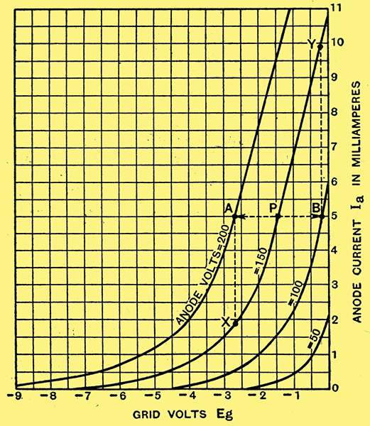
Fig. 1. - Triode. Grid volts-anode current Characteristic curves of Cossor 41MHL.
The electrons emitted from the cathode tend to form a cloud round it and have not, of themselves, any inclination to a concerted movement in one direction. The attractive field set up by the positive anode draws a proportion of them through the meshes of the grid, and on, in faster and faster flight, to the anode. But since they have to pass through the grid on their way, the number taking this trip through space can be controlled by applying as suitable potential to the grid. If this is made negative enough, it will drive back so many electrons that scarcely any will reach the anode, and the anode current will be very small. If, on the other hand, it is given the same potential as the cathode, it will offer comparatively, little hindrance to their flow, and the anode current will be large.
The way in which the anode current depends on the grid voltage is shown in the curves of Fig. 1, which are the familiar characteristic curves of an ordinary triode. The curves are made by setting the anode voltage at the figure marked against each individual curve, and noting the anode current corresponding to each one of a number of grid voltages.
The straight portions of all the curves are roughly parallel; their inclination may be read as representing the number of milliamperes increase in anode current for a reduction in (negative) grid potential of one Volt. This figure, conventionally taken at 100 Volts on the anode and zero grid voltage, is known as the mutual conductance or slope of the valve. Since it shows the extent to which the potential of the grid controls the current through the valve, it is the main index to the valve's performance. In particular, it is valuable to know how an alternating grid voltage AB such as that due to a signal will affect the anode current, set initially at P by choice of grid and anode voltages. The swing of grid voltage from A to B will clearly cause a corresponding swing of anode current from X to Y, so that the final anode current will consist of the steady current P with an alternating current of total swing XY superposed upon it.
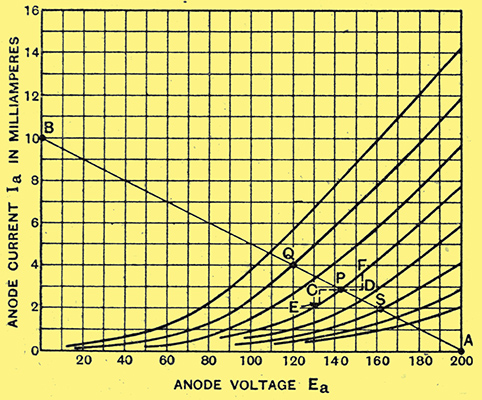
Fig. 2. - Triode. Anode current-anode Volts Characteristic curves of Cossor 41MHL.
Another set of curves can be plotted from the same data, showing the relationship between anode voltage and anode current at a series of fixed grid voltages. These curves, shown in Fig. - 2, illustrate by their inclination the impedance, or AC resistance, of the valve. It the valve is set at Ea = 143 V, Eg = -2 V (P in Fig. 2), an alternating anode voltage of 10 Volts peak will swing the anode current in sympathy from E to F, a peak swing (PE or PF) of 0.73 mA. If the application of an alternating voltage V causes a current I to flow, the resistance in the circuit must be E / I = 13,700Ω. This is; therefore, the resistance to the passage of alternating current offered by the valve when working at the grid and anode voltages symbolised at P. A little consideration will show that a steep curve implies that the valve has a low, and a flat curve a high AC resistance.
A Practical Example
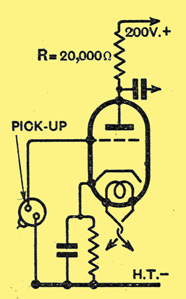
Fig. 3. - A triode amplifier for gramophone pick-up. Performance of this stage is analysed in Fig. 2.
In any practical stage of amplification it is not enough that the alternating voltage applied to the grid of the valve should develop an alternating current in the anode circuit; there must be some load in the anode circuit across which this alternating current can develop a bvoltage to feed the next valve's grid. The presence of this load modifies the shape, and especially the slope, of the curves of Fig. 1, so that the simple deduction of alternating anode current by means of the valve-curves of that diagram would lead to erroneous results in a practical case.
In the case of a stage of amplification such as that of Fig. 3, a simple construction from the curves of Fig. 2 will give all necessary information as to the degree of amplification obtainable. With an anode resistance of 20,000Ω connected between battery and anode, the anode current is zero if the voltage actually on the anode is 200 V. (Point A, Fig. 2). At 10 mA. the whole voltage of the battery is dropped across the resistance, and the anode voltage is zero (Point B, Fig. 2). The line AB is thus the load-line, to some point on which every possible voltage-current combination taken up by the valve when operating must correspond.
If the initial bias on the valve is -2 V, the working point will be at P. It the pick-up delivers a signal that swings the grid from -1 to -3 V, the anode current and anode voltage will swing up and down the line AB between the limits Q and S. The alternating anode current will thus be 1.05 mA., and the alternating anode voltage 21.8 V. The effective slope of the valve under these particular operating conditions thus amounts to 1.05 mA per Volt, and the effective amplification of the stage is 21.8 times.
The Amplification Factor
Inspection of the figure shows that if the line AB were more nearly horizontal the amplification would be greater (bigger swing in anode Volts for 1 Volt swing on the grid). A load-line passing horizontally through P would represent an indefinitely high AC load of low DC resistance (e.g., a high inductance choke) and would give an amplification of 36.7 times. This figure, representing the maximum amplification obtainable from the valve under even theoretically ideal conditions, is called its amplification factor, represented by the symbol μ. It is, in effect, the change in anode volts necessary to hold the anode current constant against a change of one Volt in the grid bias, V and so may be obtained from ordinary 'static' curves such as those of Fig. 1.
If we know the amplification factor and the AC resistance of a valve, we can easily deduce the mutual conductance A Volt of AC applied to the grid is equivalent to μ Volts at the anode, and the alternating anode current is driven through the AC resistance R0 by this voltage. Thus one volt at the grid drives a current of μ/R0 Amps. through the valve; this ratio is therefore the mutual conductance g.
In such a case as that of Fig. 3, the alternating anode current has to be driven through both the AC resistance of the valve and the load-resistance; the current is therefore μ/(R + R0) for every Volt applied to the grid. This current, in flowing through the load-resistance R, develops across it a voltage, μR/(R + R0) for each Volt on the grid; this expression, therefore, is that for the actual amplification realised in the particular stage shown, Inserting in the formula the individual figures for this case, where μ =36.7, R0 = 13,700, and R = 20,000Ω, we get 21.8 times, exactly as found graphically from Fig. 2.
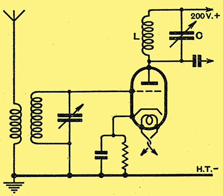
Fig. 4.- A triode amplifier for high-frequency signals. Exactly equivalent (LC replacing R) to Fig. 2.
For high amplification the requirements are evidently a valve of high amplification factor and low AC resistance, used in conjunction with a high anode load. In high-frequency amplification it is easy to build up a load of some 100,000Ω in the form of a tuned circuit, while higher loads can be obtained by special design. In Fig. 4 is shown a stage of high-frequency amplification put together on the lines of the low-frequency stage of Fig. 3; the source of signals is now a tuned circuit connected to an aerial, while the anode resistance is replaced by the tuned circuit LC, which may be reckoned as offering a load of some 100,000Ω to signals of the frequency to which it is tuned.
This amplifier, - simple and straightforward though it is - will not work. The reason is found in the capacity between anode and grid of the valve, through which energy is fed back from anode to grid in amount sufficient to set up and maintain oscillations in the grid circuit.
To prevent this unfortunate effect, it is customary to use a valve in which the capacity between anode and grid is reduced, by suitable screening, to a negligibly small amount. The screen used consists of a closely woven mesh of wire interposed between grid and anode in such a way that no part of the anode can see any part of the grid. To prevent capacity between connecting wires, either the anode (most English valves) or the grid (American valves) is connected to a terminal on the top of the bulb, as shown in Fig. 5.
In order that the screen shall be effective, it is necessary that it shall be earthed sufficiently to prevent alternating voltages due to the signal from appearing on it when a signal is applied to the grid. If it is earthed directly its potential will be approximately that of the cathode, and by screening off the DC field from the anode it will prevent this from acting on electrons in the neighbourhood of the cathode; there will therefore be no anode current, and the valve will not amplify.
Effect of the Screen
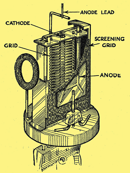
Fig. 5. - The arrangement of the electrodes in a typical screened grid valve.
By earthing the screen through a capacitor large enough to act as a virtual short-circuit to signal voltages, it becomes possible to raise the screen to a suitable positive potential. If this is done, leaving the anode, at zero potential, the cathode, grid, and screen form a triode of conventional type, the current through which is controlled by the grid-potential exactly as shown in Fig. 1.
Owing to the presence of the screen, a voltage applied to the anode will have a very small effect indeed upon the total number of electrons passing through the valve as a whole; this will depend almost entirely upon the voltage applied to the screen. Leaving this constant, the application of a steadily rising anode voltage will result in pulling more and more of the electrons through the meshes of the screen instead of allowing them to finish their travels there. The anode, therefore, robs the screen.
This effect is shown in the curves of Fig. - 6 So long as the anode is decidedly more positive than the screen it takes nearly the whole of the current; the curve for Eg = -2 shows that over the range Ea 120 to Ea = 200 the anode current only changes by 0.025 milliAmp. Over this range of anode voltages the valve has a very high AC resistance; for this particular grid-bias voltage the figure is 3.2 MΩ The curve for Eg = -1.5 is less flat; its inclination gives an AC resistance of 0.50 MΩ. Discussion of the reason for the extraordinary antics of these curves in the region of anode voltages near and below the screen voltage will be postponed; it is enough to note here that the screen-grid valve is always used with an anode voltage considerably higher than that on the screen, so that only the flat part of the curves to the right of the diagram applies to ordinary usage.
Amplification Factor of SG Valves
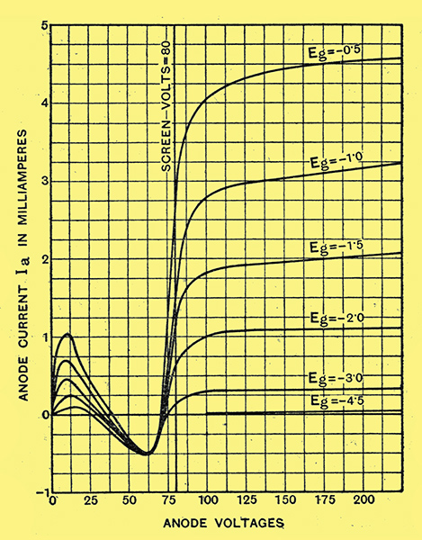
Fig. 6.- Screened Tetrode. Characteristic curves of Cossor MSG/HA.
At Ea = 200, the anode current of the valve of Fig. 6 is 2.05 mA for Eg = -1.5, but falls to 1.0 mA. for Eg = -2. The average mutual conductance of the valve over this range of grid voltages is thus 0.95 mA per half Volt, or 1.9 mA per Volt. Combining this figure with a mean value for the AC resistance - say 1.0 MΩ - we find that the amplification factor of the valve is 1,900 (μ = gR0). Some mild confirmation of this is obtained from Fig. 6 when we note that the curve Eg = -2 would apparently have to be continued the better part of a thousand Volts to the right to increase the anode current to the value obtained by reducing the grid bias to -1.5 Volts.
The Cossor MSG/HA valve referred to in Fig. 6.
With a combination of high AC resistance and high amplification factor, the behaviour of a screened valve in a receiver differs in some respects from that of a triode. Reverting, for example, to the stage of high-frequency amplification of Fig. 4. we find that the gain of the stage, assuming the dynamic resistance R of the tuned circuit to be 0.1 MΩ, will be 1900 × 0.1 / 0.1 × 1.0 if R0 = 1.0 MΩ and μ = 1900. This gain comes out at 173 times. Inspection of the figures just given shows that it is the high AC resistance of the valve that is responsible for the stage gain being only one eleventh of the rated-amplification factor of the valve.
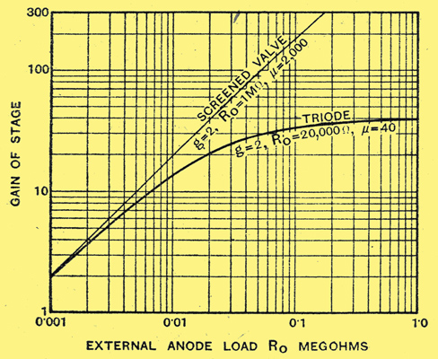
Fig. - 7. Comparison of stage-gain given by triode and tetrode, both of slope 2 mA/V, with different anode-circuit loads.
It is interesting to observe the way in in which the gain increases with anode-circuit resistance for two equivalent valves; one a tetrode and one a triode. Curves showing this are given in Fig. - 7; to make the comparison fair; both the valves taken to illustrate the point have the same slope of 2.0 rnilliAmps per Volt.
For low? Values of anode resistance, the gain given the two valves is much about the same, but the curve for the triode bends over, and for high resistances becomes very nearly a horizontal line at a height equal to the amplification factor of the valve. The curve tor the screened valve, on the other hand, is nearly at straight line of constant slope; it too, will turn over eventually, but at values of anode-circuit load far above anything practically possible. Roughly speaking, the triode tends to give a constant gain, while the tetrode gives a gain proportional to anode-circuit load. Expressed differently, the triode gives an output at more or less constant voltage, irrespective of small changes in the value of a fairly high load, whereas the tetrode passes a constant AC current through any load that is not too extravagantly high.
Looking at the formula for gain, A = μR/(R + R0), it is clear that if the anode load is low compared with the AC resistance of the valve, we may write, for approximate results, A = μR/R0, or A = gR. Thus a tetrode of slope 2.0 mA/V, used with an anode resistance of 50,000Ω, gives a gain of 100 times. (Accurate value, for the valve taken for Fig. 7, 95.3 times.) In the case of screened valves, their amplifying abilities can therefore be accurately compared by a simple comparison of slopes.
Part 2
This instalment deals with HF amplifiers, and it is clearly explained why the plain SG valve has almost completely been ousted by the variable-μ valve and screened HF pentode.
The Variable-μ Valve and the HF Pentode.
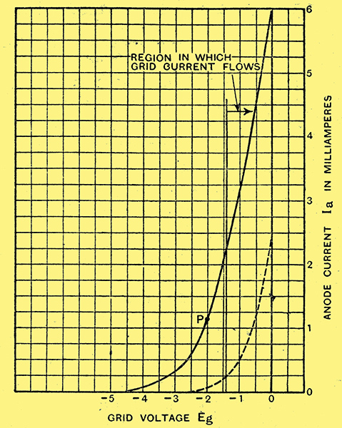
Fig. 8. - Illustrating the limited signal-handling capabilities of an ordinary SG valve (Cossor MSG/HA). Dotted curve shows effect of reducing screen voltage.
The simple screened valve, as discussed before, possesses certain disadvantages of its own from which the triode is more nearly free. The triode, especially the low-impedance triode, has a grid-Volts/anode-current curve (type of Fig. 1) which possesses a long straight portion. Since changes in anode current are strictly proportional to changes in grid voltage only so long as the portion of the curve representing their relationship is perfectly straight, it follows that if a signal is of big enough amplitude to carry the grid-voltage momentarily over the limits of the straight portion of the curve the amplified signal will be distorted.
Inspection of Fig. 8, which shows the curve of a typical medium-impedance screened valve, shows that the usable portion of the curve, lying between the minimum bias-point required to suppress grid-current (about -1.4 V) and the bottom bend, is very restricted. If we suppose that the next valve is a detector requiring 3 Volts to operate it, then if the gain given by the screened valve in conjunction with the tuned circuit providing the load in its anode circuit were 60 times it would never be necessary to give the screened valve a signal greater than 1/20th Volt. For so small a voltage-swing as this the curve shown is very much more than adequately long.
But in practice it is quite impossible to ensure that the valve shall never receive more than this carefully controlled signal. Even when quite widely detuned from the local station, the aerial circuit will give the valve far more than 1/20th Volt, and when fully tuned in the signal may amount to five Volts or more. If the working point is at P, the grid will be swung from -7 V to +3 V, which will quite evidently lead to considerable distortion of the received wave-form. To make matters worse, the detector valve of the set would be hopelessly overloaded long before the signal input had risen to such values as these, so that it would already have been necessary to apply the volume control. This, in the case of the screen-grid valve, usually takes the form of a reduction in screen-voltage, which means that the full-line curve of Fig. 8 will have been replaced by some such curve as that shown dotted. This change of operating curve is hardly one that assists the valve to deal, without distortion, with a large signal input. The effect of this distortion, if the valve were dealing with a simple unmodulated carrier wave, would be unimportant, for distortion of a simple wave-form merely means the importation into it of harmonics. Since these must be some whole number multiple of the initial frequency, the tuned circuit following the valve would be so far detuned from them that they would develop no appreciable voltage across it, and so would be automatically filtered out. (Compare the effect of distortion in a low-frequency amplifier, which is usually designed to amplify all frequencies equally.
In an ordinary practical case of wireless reception the signal applied to the first valve is very complex. The required station gives a carrier-wave modulated at a number of frequencies - itself a pretty complicated matter - and there are in addition similar signals of more or less intensity from each of a number of other transmitters. Of these the strongest is likely to be the local station.
Cross-modulation Explained
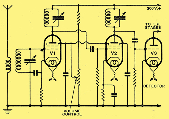
Fig. 9. - A typical 2-HF receiving circuit with ordinary SG valves; volume control by variation of screen voltage.
Suppose that a receiver built to the skeleton circuit of Fig. 9 is tuned to a distant station removed in frequency from the local station by 36 kHz (four channels). We may assume that the combined selectivity of the three tuned circuits is enough to reduce the local station to inaudibility when they are all tuned 36 kHz away from it. Yet at the grid of the first valve, which is protected from the local station by only one tuned circuit, there may well be a very large signal from this station. Enough, it may be, to cause this valve to overload, distort; and add unwanted harmonics to every signal that it receives.
Of the various unwanted components of the distorted anode current most are harmless, having frequencies that cannot pass, through the subsequent tuned circuits to the detector valve. One, however, consists of the carrier-wave of the desired station, that to which the set is nominally tuned, modulated with the programme of the local station. Since the set is tuned to this carrier, it will pass through the remaining two tuned circuits, being amplified by the second screened valve on the way and will arrive at the detector valve, with the result that the local station will be heard at the same time as that desired. This form of interference, which is known as cross-modulation, can be recognised by the disappearance of the programmes from the local station if the station to which the set is tuned switches out its carrier-wave.
This superposition of unwanted upon wanted station takes place in the first valve; in consequence, the initially high selectivity of the set will fall to that of a set with only one tuned circuit as soon as the first valve is overloaded enough to cause distortion. In the absence of a local station of any great power, cross-modulation naturally does not occur, because the first valve never receives a signal powerful enough to overload it.
The Variable-μ Valve
There are two possible ways in which this lack of selectivity can be combated. One consists in making sure that as soon as the set is tuned away from the local station its signals are sufficiently excluded from the grid of the first valve to prevent overload. This can be done by using two (or more) tuned circuits before the valve - the well-known band-pass filter cure for cross-modulation.
The other line of attack involves replacing the first valve by one which does not overload so readily as an ordinary screen-grid valve, so that quite large voltages from the local station can reach its grid without causing this signal to introduce distortion. Further, some method of volume control other than that of reducing screen-voltage, which inevitably reduces the signal-acceptance of the valve, must be provided.
Both these latter conditions are satisfied by the variable-μ valve. Constructionally, this differs from an ordinary screen-grid valve only by having a control grid which has a mesh of uneven pitch. This results in the valve having two independent characteristics; it behaves, in fact, like two valves in parallel. One of these would be an ordinary screen-grid valve of high-amplification factor, the other a screened valve of very low amplification factor, requiring therefore a very heavy negative bias on the grid to reduce the anode current to zero.
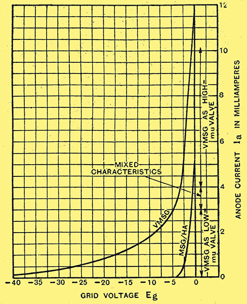
Fig. 10. - Characteristics of variable-μ valve (Cossor VMSG) compared with ordinary SG valve.
A curve of such a valve is given in Fig. 10, together with that of an oridnary screen-grid valve (re-plotted from Fig. 8) for comparison. As the bias on the variable-μ valve is increased, the anode current at first drops rapidly, but at about -4.5 Volts, the point at which the current of the ordinary valve cuts off completely, the variable-μ valve is still passing 3 milliamps. From this point on it behaves as a valve of so low an amplification factor that it is necessary to increase the bias to over 40 Volts to reduce the anode current to zero. The current-ranges over which the valve has high-μ and low-μcharacteristics are roughly indicated on the right of the diagram.
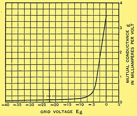
Fig. 11. - How the mutual conductance of a variable-μ valve (Type VMSG) is affected by alterations of bias.
The great length of this curve shows that the valve will handle very much larger signals than the ordinary screened valve before it introduces cross-modulation. Further, it will be noticed that the curve gets progressively less steep as more bias is applied. That is, the slope of the valve, and hence its amplifying abilities, are reduced by increasing the bias. This offers the desired feature of a volume-control independent of screen-voltage, for all the control that could possibly be desired is available by mere change in bias voltage. This is illustrated in the curve of Fig. 11, which shows the variation of the slope of the valve with bias. Roughly, the gain of the stage in which this valve is incorporated can be varied over a range of 50 to 1 by change of bias. This is plenty for a single-stage set; if two stages are used the control covers a range of 2,500 to 1.
With strong signals it is necessary to accommodate, without flow of grid current, a larger voltage-swing than is necessary when receiving small. signals. The volume-control by bias, in which the working point of the valve moves progressively down the curve as the signal gets stronger, automatically allows for this.
Secondary Emission Effects
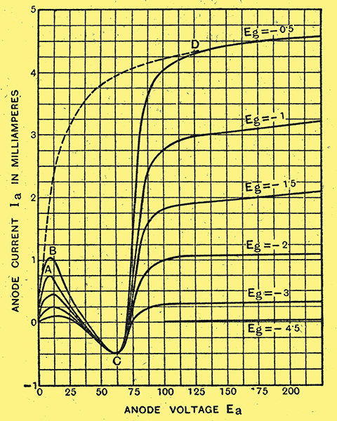
Fig. 12. - The dotted line shows the anticipated characteristics, from simple theory, of an SG valve, while the realised characteristics of the actual valve are indicated in full lines.
It is evident, of course, that the curve of Fig. 10 is not a straight line over its whole length. Some slight distortion must therefore still remain when a really strong interfering signal, of the order of 5 Volts, is being received. Even so large a signal as this, it must be noticed, only involves a comparatively small part of the curve, over which the departure from a true straight line is nowhere very serious. The full curvature, as the eye appreciates it by looking at the diagram, never comes into effect at all. Were the curve a straight line, volume-control by bias would obviously cease to be possible, since the slope of the valve would be the same throughout.
In practice, it is found that the variable-μ valve, even though not theoretically perfect, is sufficiently so to provide a complete cure for cross-modulation in all reasonable circumstances. As a result, it has almost entirely replaced the ordinary screen-grid valve for all purposes save that of detection. The peculiar shape of the curves connecting the anode voltage of a screen-grid valve with the anode current has already been remarked upon. If the effect of slowly raising the anode voltage from zero up to and beyond the screen voltage consisted only in the progressive increase in the number of electrons drawn through the screen to the anode, one would expect the curve to have some such shape as that shown dotted in Fig. 12. Here the anode current is depicted as rising regularly with anode voltage until the latter reaches that of the screen, after which, the anode by now taking practically all the electrons, the current is shown as rising, only very slowly. The curves of Fig. 6, reproduced in full line in Fig. 12, represent the observed behaviour of an actual valve.
The failure of the practical curves to reproduce the admirable simplicity of the theoretical one is due simply to the omission from the theory of the process of secondary emission. When an electron strikes a piece of metal at speeds over certain limit it is liable to dislodge by its impact one or more electrons from the metal itself. These electrons, once liberated into, free space, will be attracted to the most positively charged object within their range.
With this new phenomenon in mind, let us trace the course of the curves. On first applying a voltage to the anode, a small current appears. For a certain distance the dotted curve is followed, but at A the observed curve bends sharply away. This corresponds to the beginning of secondary emission from the anode, the released electrons travelling to the more positive screen. The net anode current is naturally. reduced by these lost electrons.
The HF Pentode
Increasing the anode voltage above that at B results in more electrons reaching the anode, but each additional electron now knocks out more than one on its arrival, and all these reach the screen, which is still at a much higher potential than the anode. The current therefore decreases with rising voltage and continues to decrease down to the point C. The fact that the current at C is negative merely implies that the impinging electrons displace secondary electrons at the rate of more than one per head. Beyond C, where the voltage at the anode is not much less than that at the screen, an appreciable proportion of the electrons ejected from the anode are beginning to return to it instead of to the screen. This proportion rapidly rises as the anode voltage reaches and exceeds that on the screen until finally, at D, all secondary electrons return to the anode and the observed curve has rejoined the dotted one.
From the resulting curves it is clear that violent distortion is likely to occur if the alternating voltage developed on the anode during the receipt of a signal is allowed to be great enough to swing the anode momentarily down to a voltage near that of the screen. Nor can a low screen-voltage be used to minimise this effect, for this would reduce the voltage-handling capacity of the valve on the grid side, as we have already seen. To avoid distortion when has screened valve is called upon to handle a large voltage in its anode circuit it is therefore necessary to suppress this secondary emission.
This is done by inserting an extra electrode between screen and anode and connecting this electrode, called the suppressor grid, to the cathode. A secondary electron ejected from the anode is now protected from the attractive field of the screen, While still feeling the pull of the anode. It therefore returns to the latter, leaving the total anode current neither larger nor smaller as the result of its little trip into space.
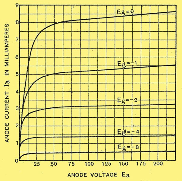
Fig. 13. - Avoiding secondary emission; the curves of a variable-μ screened pentode (Cossor MVS/Pen). The 'kinks' shown' in Fig. 12 have disappeared.
A screened valve built with the additional suppressor grid has five electrodes in all, and so is known as a pentode. That the suppressor really does suppress secondary emission can be seen from the curves of Fig. 13, which relate to a screened pentode. In general shape they agree quite well with the dotted curve of Fig. 12, deduced for a screened valve without taking secondary emission into account.
Part 3
This segment gives just that essential information about the pentode which enables that somewhat tricky but highly popular valve to be used to best advantage.
Pentodes, Screened and Unscreened
Just above it was pointed out that the screened pentode, as used for high-frequency and intermediate-frequency amplification, may be regarded as a simple screened tetrode from which the evil effects of secondary emission have been removed by the introduction of the suppressor grid between screen and anode. As a consequence, the irregularities of the anode-Volts/anode-current curves that are typical of the tetrode do not occur in the pentode curves Fig. 13.
From these curves, which were taken with the screen held at 100 Volts positive, it will be seen that there is no sharp change in the behaviour of the valve when the voltage on the anode drops to that on the screen. On the contrary, the nearly horizontal part of the characteristic, which in the closely corresponding tetrode is the only portion useful for ordinary purposes, extends to the left to cover the anode voltages as low as 50 Volts or below. Thus the alternating voltage on the anode due to the signal may swing the anode momentarily to potentials below that at which the screen is held without causing overload or distortion.
In brief, one may sum up the screened pentode as simply an improved version of the ordinary screen-grid valve; it will do all that the screen-grid valve will do, and, in addition, will cope without difficulty with tasks that are beyond the capacity of the ordinary tetrode. But substitution of a screened pentode for a screen-grid valve, in a set where the latter is working well within its capacity, will make no appreciable difference to results.
If it is permissible for the anode voltage to fall to that of the screen, it should be equally permissible for the screen-voltage to be raised to equal that of the anode. Although screened pentodes, being intended as replacements for screen-grid valves, are designed for a fairly low screen voltage, a second class of pentodes, the output pentodes, are not.
These valves are intended to handle without distortion the power needed for operating a loud speaker. The limitation of anode-voltage swing typical of the tetrode clearly rules out this type of valve, but the pentode can fulfil the task admirably.
The Output Pentode
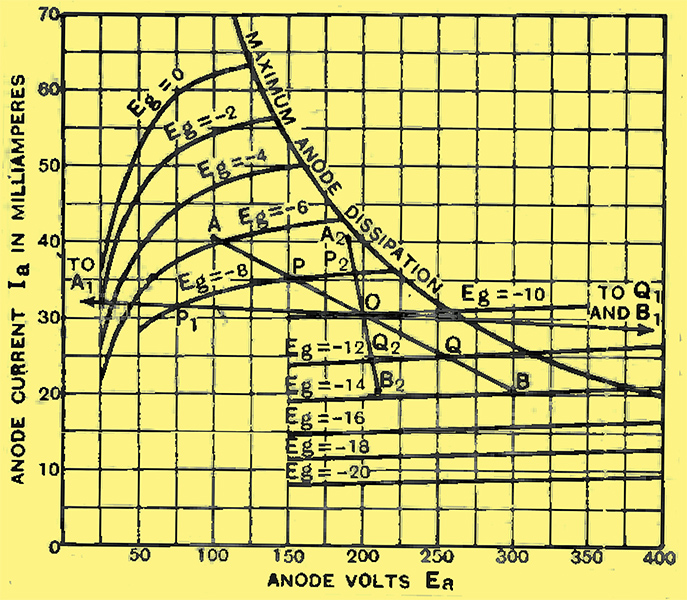
Fig. 14. - Curves of a typical output pentode (Cossor 41MP/Pen). Screen voltage is maintained constant at 200 Volts.
An output pentode differs from a screened pentode in two major respects. To provide adequate power for the speaker it is necessary that the valve should take a fairly large standing current; this is looked after by designing the valve to operate with its screen at the same voltage as its anode. The other difference is bound up with the fact that electrostatic screening between anode and grid is not nearly so necessary in low-frequency amplifiers as in those designed for operation at high-frequency. In an output pentode, in consequence, all connections to the various electrodes are taken out through the base of the valve, and the terminal on the top of the bulb, necessary in the screened valve to ensure isolation between anode and grid circuits, is discarded.
Fig. 14 gives the anode-Volts/anode-current characteristics of an output pentode. These curves were taken with the screen held at 200 Volts, and show the characteristic shape of all pentode curves. Since, for reasons of valve-life, the mean power dissipated at the anode of this particular valve must not be allowed to exceed 8 Watts, the pairs of values of anode voltage and current giving this dissipation have been plotted, as a guide to safe operation, on the diagram. The bias-point must, therefore, always be chosen so as to keep the working conditions on the left of the curve marked 'Maximum Anode Dissipation'.
From these curves the performance of the valve as an output valve can be determined. The first point to consider is the load into which the valve is to work; that is, the value of the impedance to be connected in its anode circuit. Suppose it is intended to work the valve at Ea = 200, Es = 200, Eg = -10, corresponding to the point O on Fig. 14. The load will be a loud speaker which has a low resistance (for simplicity, we will assume zero resistance) to the steady direct current, but a high impedance to alternating (signal) currents. This high impedance can be considered, for theoretical purposes at any rate, as a pure resistance if we make the assumption that the signal voltage developed across it drives through it a signal current which is entirely consumed either in driving air backwards and forwards by moving the cone or in frictional and other losses resulting, eventually, as heat. This assumption, though perhaps not completely justifiable, is made in nearly all cases in examining the behaviour of an output valve.
Since the load is assumed to have no DC resistance, the voltage actually on the anode of the valve will be that of the anode-current supply source namely, 200 Volts. If a signal sufficiently strong to swing the anode current by 10 milliamps is applied to the grid, the anode voltage will swing to an extent depending on the signal-frequency impedance of the load. If this is 10,000Ω the anode voltage will swing by 100 Volts, which means that in response to the signal the anode voltage and anode current will swing over the range of values given by the line AB. These two points are fixed by the fact that at A the anode current is 10 mA. greater, and the anode voltage 100 Volts less, than at O, while at B the current is 10 mA less, and the voltage 100 Volts higher than at O. The line AOB, in fact, is the load-line, corresponding to that discussed in Part 1, in connection with a triode. The sole difference between that load-line and this lies in the assumption now made that the load has a resistance towards AC and none towards DC, whereas in considering the resistance-coupled triode stage the load was a true resistance, equally effective towards both steady currents and those due to the signal.
As before, the amplification obtained from the stage may be seen by noticing the points where the load-line cuts the successive curves corresponding to various values of bias. A signal swinging the grid from -8 V to -12 V will cause the anode to swing between points P and Q, representing a voltage change at the anode of 255 - 155 =100 Volts. The-amplification of the stage will thus be 100/4 = 25 times. Just as with the resistance-coupled triode or tetrode, the amplification will depend on the value ot the load, rising as this is made higher. Comparison of the load-line discussed with those for 1,000 and 100,000Ω (A2B2 and A1B1 in Fig. 14) shows this quite clearly. For the low load the gain is only 2.75 times, while for the higher it rises - (with much distortion) to some unspecified value in excess of 60 times.
In this case, however, it is. not enough only to develop a high voltage across the speaker, for this requires power to operate it. This power depends on the product of alternating voltage across the speaker with the alternating current driven through it by this voltage, and it will be seen at once by comparison of the three load-lines that although a higher load develops a higher voltage, the current through the speaker is less. With a very high load (line approaching the horizontal) the current through the load would be trifling even though the anode voltage were to swing right down to zero; the power, therefore, could only be small. Similarly if the load were very low (line approaching the vertical) the voltage developed across the load could never be large, even though the current were to swing right down to zero; once again, the power could only be small. It will be evident, therefore, that it is necessary to choose the correct load for the pentode with some care, making the best possible compromise between the conflicting requirements of high current and, high voltage in such a way that their product, representing the power, is at its maximum.
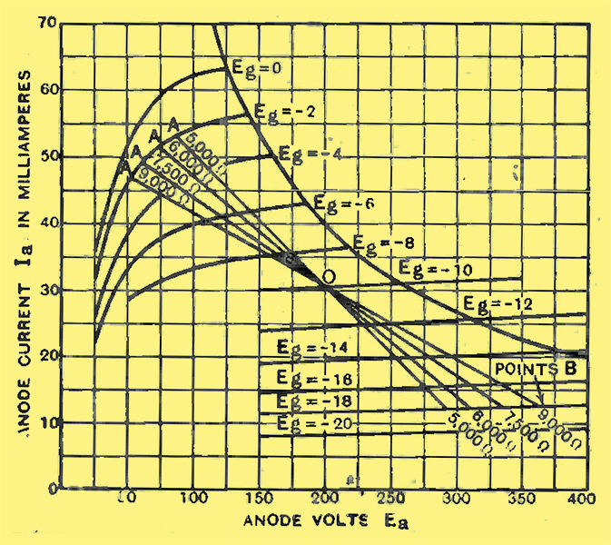
Fig. 15. - Lead lines of output pentode; the 7,500 Ω line corresponds to zero second harmonic,distortion, and is therefore at least approximately the best to use.
How this is done is shown in Fig. 15 where, for the same steady-current conditions as those taken in discussing Fig. 14, four load-lines are drawn. These represent, in order from steep to flat, loads of 5,000, 6,000, 7,500, and 9,000Ω. In considering the available output from the valve, it will not be safe to assume that the grid can be swung to zero, because the valve considered belongs to the class of indirectly heated pentodes, in all of which grid-current, with its attendant damping of the input coupling (resistance or transformer), begins to flow while the grid is still negative, With this in mind, we will limit the grid-swing, in the positive direction, to -2 Volts; this value is chosen for our discussion chiefly because there is a curve for it. With an initial bias of -10 Volts, a swing to -2 Volts on the one side will carry the grid to -18 Volts on the other. It remains to see what load gives the maximum output together with unnoticeably low distortion when the grid is given this peak signal of 8 Volts.
Harmonic Distortion
In pentodes, it is found that a type of distortion equivalent to the introduction of the third harmonic of the signal sets the limit to the available power. Further, it usually so happens that for a signal and a load with which the amount of second harmonic distortion introduced is exactly zero, the third harmonic has just about reached its maximum permissible limit. The condition for zero second harmonic is that the distance between the working point O and the point where the load-line cuts the curve representing the maximum positive grid voltage reached (A) should be exactly equal to the distance between O and that where the line cuts the curve representing the maximum excursion of the grid in a negative direction (B). For the lines on Fig. 15 representing loads of 5,000 and 6,000Ω OA is longer than OB, while for the 9,000Ω line OA is shorter than OB. The two halves of the 7,500Ω line are, however, almost identical in length. From this we conclude that it is only with this exact load that the full grid-swing from -2 V to -18 V can be applied to the valve without causing audible distortion.
Taking this load, 7,500Ω, as correct, we see that the grid-swing of ±8 V swings the current between the limits 49 and 12 mA, while the voltage across the load swings from 340 to 60 Volts.The peak signal current is thus 37/2 or 18.5 mA, and the peak signal voltage 280/2 or 140 Volts. Corresponding, RMS values are found by dividing each of these by √2, and the product of the resulting; figures, (140 × 18.5/2 = 1,300, is the power in milliwatts that can be delivered by the valve under these conditions.
Maximum Power Output
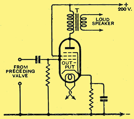
Fig. 16 - A modern pentode output stage, in which the valve load is adjusted to the required value by correct choice of the ratio of the output transformer T.
To find the absolute best conditions of operation, including load, bias, and standing current, to ensure that the last possible milliwatt of power is extracted from the valve, it would be necessary to repeat the analysis already made for other bias values at the anode voltage intended to be used, and to make a more detailed examination of the curves with a view to determining the exact percentage of the third harmonic introduced. The exact optimum load and bias could then be definitely settled by comparison of the various figures for available output at the permitted maximum of total distortion. Such an analysis is extremely long and tedious; the results of it are given away with every valve on the instruction leaflet. We will therefore assume that the analysis has been performed, and that the result of it is the 7,500Ω load-line shown on Fig. 15.
Two useful figures, by which the performance ot this valve can rapidly be compared with that of others, can be extracted from the details of this figure. Of these the first is the sensitivity, expressed in milliwatts per Volt squared of signal applied to the grid, which shows the output that is yielded in return for a signal input of 1 Volt. Since the input voltage for1,300 mW is 8/√2 V RMS, we find that the sensitivity of this valve, operated under the conditions and with the limitations described, is 1,300/5.32 or 40.6 mW/V2.
The efficiency of -the valve as a converter of DC to AC power can also be found. The anode circuit consumes 30.5 mA. at 200 Volts, drawing, therefore, 6,100 mW of DC power. The efficiency is, therefore, 1,300/6,100 = 2I.3%. If the power available had been reckoned in the usual manner, allowing the grid to swing to zero bias, the power would have been 2,000 mW and the efficiency 33%; by a slightly more careful choice of operating conditions this might have been pushed up to 40% or so.
Such figures as these cannot even be approached by the triode valve, which yields efficiencies of the order of 15%; this is one of the reasons why the pentode is generally chosen as the output valve for a modern set. The other main reason for this preference for the pentode lies in its sensitivity; it requires a much smaller signal-voltage to drive it than does the triode. In the early days of the pentode it was sometimes claimed that its substitution for a triode was equivalent to adding another stage of amplification to the set; though its superiority is not, and never could be, as great as this extravagant claim implies, yet the increased sensitivity it confers upon a receiver is very evident indeed.
To set against these advantages we have to remember that the pentode requires a rather exact adjustment of load impedance to enable it to give its full output without distortion. The triode, on the other hand, is very much more tolerant in this respect, as can be proved by drawing the appropriate load-lines across, the curves of an output triode and analysing the resulting figure as we have done in the case of the pentode. In the days when the moving-iron speaker was still widely used, this point told heavily in favour of the triode on account of the variation of speaker-impedance with frequency, which meant that correct loading could never be attained over the whole frequency-range. Now that the moving-coil instrument, with its much more constant impedance, is almost universally used, this advantage of the triode is much less weighty, and the extra sensitivity and efficiency of the pentode have resulted in its almost universal adoption.
Part 4
This part deals with superheterodyne frequency-changers, and describes practical methods of 'mixing' the incoming signal with locally generated oscillations. Diode detectors and multiple valves are also treated.
Valves for Special Purposes
In the preceding articles of this series we have discussed types of valve used simply for amplification. There still remain other functions which are performed in the set by valves.
In a superheterodyne receiver the signal, with or without preliminary amplification, has its frequency changed from that at which it is received to another for which the amplifying portion of the set is designed. It is not proposed, since we are dealing with valves, to discuss at any length the process of frequency-changing, but it is a necessary preliminary to remind readers that the new frequency is built up by combining the original signal current or voltage with a second high-frequency current or voltage generated locally. The results of the combination include new currents whose frequency is equal to the sum, and to the difference, of the two original ones. Of these two the succeeding amplifier is designed to accept and amplify one, that usually chosen being the difference-frequency.
Two stages are essential in this process; first, the generation of the local oscillation, and, secondly, the mixing of the two. This mixing cannot be carried out simply by passing the two currents through the same circuit, for then, though both are present, they are independently present in the sense that neither is the least affected by the other. The mixing required before the new frequency is formed is more intimate than this; the one current must so modify the circuit that the other is differently amplified as a result of its presence. Such modifications of circuit conditions can only take place in a valve, which is known, according to the way in which it is used, either as a first detector or as a modulator.
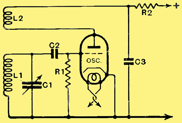
Fig. 17. - A simple generator of oscillations.
The generation of the local oscillation is generally carried out by a triode connected in some such way as shown in Fig. 17. The coupling between the tuned coil L1 in the grid circuit and the untuned coil L2 in the anode circuit is so adjusted that the energy fed back from L2 into L1 is always in phase with that already there. As a result, if any trifling disturbance in the valve or tuned circuit puts a momentary positive voltage on the grid, this voltage is amplified by the valve and fed back from L2 into L1 in such a way as to increase at that instant the positive voltage already there. Owing to the fact that any kind of disturbance in a tuned circuit shocks it into momentary oscillation, the positive voltage accidentally evoked must always be followed at a time interval depending on the frequency to which L1 is tuned by a corresponding negative voltage. This, in its turn, is enhanced by energy fed back from the reaction coil L2.
If the energy so introduced into L1 is greater than that lost owing to its resistance, the momentary oscillation, instead of dying away, will grow. Its growth will continue as long as more energy is fed back in each second than is lost in that time. In practice the grid current flowing during the positive half-cycle develops across R1, a voltage which biases back the valve and reduces its amplification, until at some amplitude of oscillation, depending on the resistance of L1, the mutual inductance between it and L2, and the characteristics of the valve, an equilibrium is reached and the amplitude of the oscillation remains unchanged.
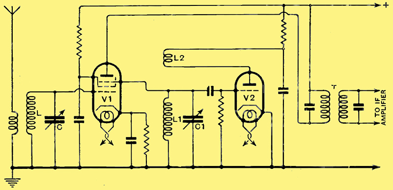
Fig. 18. - A two-valve frequency-changer, in which oscillator voltages are applied to the suppressor grid of a screened pentode detector.
Fig. 18 shows one of the many ways of combining signal and local oscillation. The latter, generated by the triode V2, is directly applied to the suppressor-grid of the pentode V1, the signals meanwhile being applied to its ordinary control-grid. The characteristics of a screened pentode can be varied by altering the voltage on its suppressor; in the frequency-changer shown the characteristics of V1 are being varied at the frequency of the local oscillation. The required new difference-frequency is thus produced, and is selected from the many currents of various frequencies present in the anode circuit of V1 by the tuned intermediate transformer T.
Combined Detector-oscillators
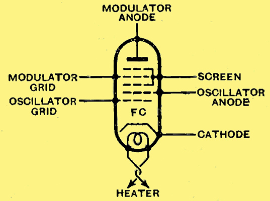
Fig. 19. - Arrangement and functions of the various electrodes in a pentagrid frequency-changer.
The pentagrid has been developed to provide a single valve that will combine the functions of local oscillator (V2) and mixer valve or first detector (V1). As its name implies, it contains five grids, in addition to the normal anode and cathode, These grids are disposed and used in the manner shown in Fig. 19, it being understood that the whole structure is cylindrical, with a central cathode round which the grids are arranged in the order shown.
It is simplest to regard this rather complex valve as a triode (two innermost grids) surrounded by a screen-grid valve (two outermost grids and anode) with an electrostatic screen (central or third grid) between the two valves. In use, the inner-most grid and the one next to it are connected exactly as the grid and anode of the oscillator valve already discussed in connection with Figs. 17 and 18; these two electrodes are, in consequence, usually referred to as oscillator grid and oscillator anode.

Fig. 20. - A pentagrid valve and its circuits.
Since all the electrons reaching the anode and the other electrodes of the outer or modulator valve have to pass through the triode, it is evident that when the latter is made to oscillate, as in Fig. 20, the total current of the modulator portion will rise and fall in time with the oscillation. As the slope of any valve depends largely upon the current through it, this means that the alternating anode current produced by the signal applied to the modulator grid will rise and fall at the frequency of the oscillation. In this way the intimate mixing of signal and oscillation is achieved, and the difference-frequency current makes its appearance, and is selected by the intermediate transformer T of Fig. 20.
Except for the fact that in the case of the pentagrid the oscillation can control the electron-stream through the mixer-valve directly, while in the case of the two-valve frequency-changer of Fig. 18 the control had to be done via the pentode's suppressor grid, the operation of the two circuits of Figs. 18 and 20 is much the same.
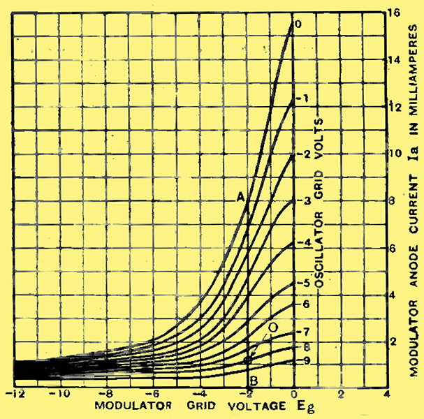
Fig. 21. - Pentagrid characteristics; curves for different values of oscillator grid bias. Typical operating point marked O.
The way in which the oscillator controls the modulator portion of the pentagrid is well shown in Fig. 21. All these curves, which show the variation of modulator anode current with modulator grid voltage, were taken with the same operating voltages on the modulator itself. Each, however, refers to a different fixed bias on the oscillator grid. Comparison of the curves thus shows the influence of the oscillator portion upon the outer tetrode.
The operation of the valve can be followed quite well from the curves. If we assume that the oscillation of the triode is such as to produce a total grid-swing of 16 Volts, then, since the valve will bias itself back by grid current through R (Fig. 20) until only the extreme positive peaks draw grid current, the oscillator grid will have a mean bias of approximately 8 Volts. If the modulator grid is biased to -2 Volts, the characteristics of this valve will be swung by the oscillation through all the values symbolised by points on the line AB in Fig. 21.
The inclination of the curves shows very clearly that at moments when the oscillator grid is most negative the modulator slope is practically zero, while when the oscillator grid approaches zero potential the modulator slope is high. Thus the amplification given by the valve to the signal applied to the modulator grid will increase and decrease rhythmically with the rise and fall of the oscillator grid voltage caused by the oscillation itself, and the difference-frequency required is formed in the anode circuit.
The Diode Detector
The diode is the oldest and simplest type of thermionic tube, consisting simply of a cathode and an anode. The term valve, which so ineptly describes the modern amplifying tube, was originally invented for the diode in view of the fact that current can only pass through it in one direction.
The diode cannot amplify, but it can detect; this, indeed, was its original use when it was the only kind of valve known. The later introduction of the triode, which can both detect and amplify in one operation, caused the diode (except as a mains rectifier) to disappear entirely for a time. Modem conditions, however, are bringing it back into favour.
Until automatic volume control was demanded by the user of the set, no great advantage was to be had by amplifying the received signal to more than a volt or so at most before rectifying it. The triode, first as grid detector and later as 'power' grid detector, therefore fulfilled all possible needs, in spite of the fact that it would overload and distort on strong signals. No serious inconvenience was caused by this, because sufficient LF amplification was provided in the set - usually by the detector itself-to ensure that adequate output could be had from a signal small enough to be handled without distortion by the detector.
But if automatic volume control is desired, it becomes desirable to be in a position to rectify a signal large enough to produce a DC voltage that, when fed back as. bias to variable-μ valves used as high- and intermediate-frequency amplifiers, will reduce their amplification almost to zero. For this the DC voltage needed is about 15 Volts or more, which requires for its production a peak HF voltage of about the same, or a modulated HF voltage up to double this value.
No ordinary detector will stand up, without distortion, to an input of this magnitude on account of the enormous anode current swings at high frequency that are produced in response to such a signal. The low-frequency component, which even at 100% modulation only has half the amplitude of the modulated carrier, is more readily dealt with; in any case, the question of handling it is an ordinary problem of LF amplification.
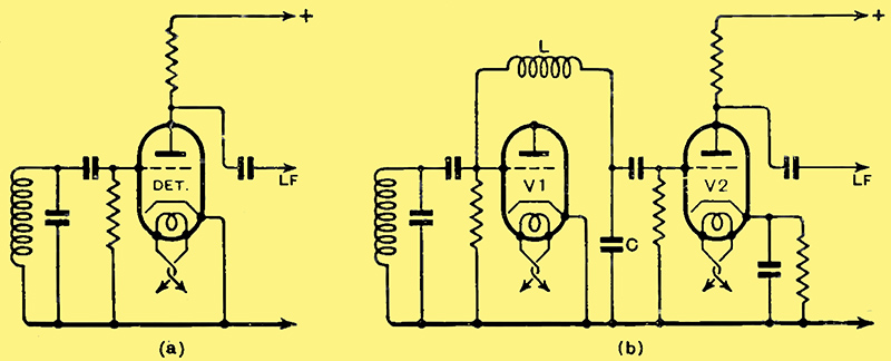
Fig. 22. - In diagram (a) the grid rectifies and also controls anode current to provide LF amplification. In diagram (b) rectification and amplification are effected by separate valves; the grid of V1 rectifies, whilst that of V2, isolated from LF voltages by the filter LC, controls LF amplification.
It becomes necessary, therefore, to take steps to remove the high-frequency component from the anode circuit of the detector; this can be done, as suggested in these pages more than three years ago, by transferring the low-frequency component, through a filter to remove high-frequency currents, from the grid of the valve used as grid detector to the grid of a second valve used as a pure LF amplifier. Such a circuit is shown in Fig. 22b, in contrast to the simple grid detector of Fig. 22a. The two-valve system will handle a much larger input voltage than its single-valve counterpart; in fact, the limit is set entirely by the overloading of the second valve, for the first has so high a grid resistance that it takes quite a small current even when given an enormous signal. With the interposition of a volume control between the two valves to control the LF input reaching the second, we are in possession of a system that will handle faithfully signal inputs up to 100 Volts at least without any signs of distortion.
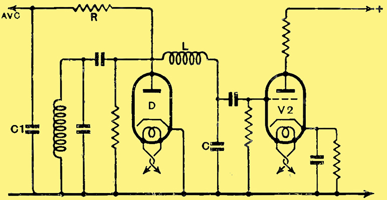
Fig. 23.- Essentially the same circuit as that of Fig. 22b, but modified to provide simple AVC. The extra components R and C1 act merely as a filter, barring both HF and LF energy from the AVC line.
From Fig. 22b it is easy to develop the simple AVC circuit of Fig. 23. In this the detector valve, of which only the grid was used in Fig. 22b, is replaced by a diode, and, while the modulation-frequency component of its output is fed forwards to the LF amplifier V2, the direct-current component, in the form of the rectified voltage across the 'grid' leak, is fed back to bias earlier valves. The disadvantage of this simple circuit is that the earlier valves begin to receive a bias as soon as any signal reaches the diode D, so that by the time the signal is powerful enough to operate the loud speaker, the sensitivity of the set as a whole has been very appreciably reduced.
Delayed AVC
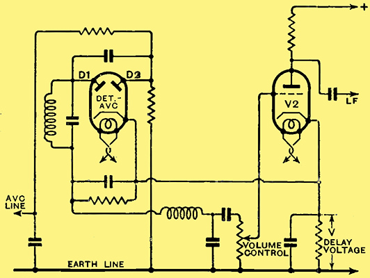
Fig. 24. - Delayed AVC circuit. If the bias voltage of V2 is suitable also as delay voltage both valves may be combined as a double-diode-triode with common cathode. But a separate double diode is is needed when different cathode potentials are desired.
This and other AVC circuits are possible by using a double diode in conjunction with any desired LF amplifier; if strong enough signals are available at the diodes V2 may even be the output valve. Since it is usual to connect the cathode of the diodes to that of the succeeding valve, and since, further, the emission required from the cathode for adequate performance on the part of the diodes is only a few milliamperes, it is possible to sacrifice a small portion of the cathode of V2 and to use this for the diodes. Thus are born double-diode-triodes) double-diode tetrodes and double-diode-pentodes, with their bewildering seven-pin bases and grids connected to top caps.
Of these the only one that is anything more than a combination of two diodes in the same bulb as a more or less standard valve is the double-diode-pentode. This has been designed for the specific purpose of providing correction, on the audio-frequency side, for the small differences in volume between station and station that remain even in a set fitted with AVC of normal type.
AVC in LF Circuits
If, with the circuit of Fig. 24, a 3 Volt signal is required at the diodes to give full loud-speaker strength, and if, further, a bias of 15 Volts is required to reduce the gain of the variable-μ valves preceding the diode to a suitable level for handling the signals of the local station, the signal voltage arriving at the diodes when the local station is tuned in will be 18 Volts or six times that necessary for full output. Either a volume-control will have to be used, or there will be overloading.
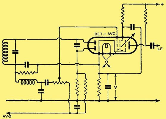
Fig. 25. - Double-diode-pentode used for delayed and corrected AVC. The pentode LF amplifier has a special variable-μ characteristic, and is biased from the AVC line. Its amplification falls as the rectified signal rises, providing an LF output that is independent of HF input.
In the DD/Pen the pentode used as LF amplifier after the diodes has a variable-μ characteristic on the lines of those discussed in connection with screened valves for high-frequency amplification, and this characteristic is so computed that by applying the AVC voltage to the pentode portion of the valve the LF gain is reduced to compensate for the rising signal input. The circuit used for this valve is shown in Fig. 25, where the grid-leak of the pentode is taken to the AVC line.
Like this valve, all the double-diode composite valves have no general applicability in the sense that they can be used as raw material for the design of a stage to suit our needs. They are essentially combinations built up to fill a definite place in a receiver of particular design. Their consideration at any length as even the trend of the present article must have shown any observant reader would lead us away from valves into the most intimate details of receiver design - with which we are not at present concerned.
|