|
Designing Distortionless Apparatus.
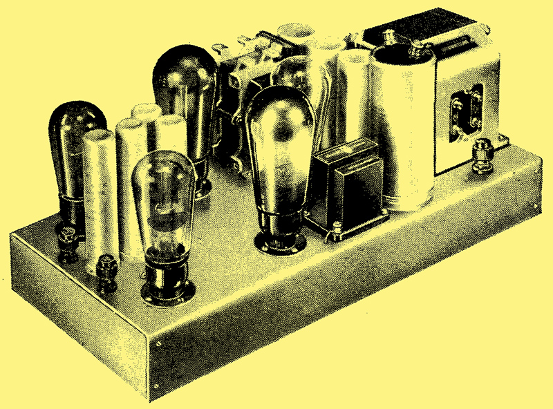
A high quality amplifier with two push-pull stages.
In the reproduction of music and speech for entertainment purposes the attainment of a high standard of fidelity is of paramount importance, and with suitable equipment it is possible for this to be so high that it is easy to mistake the reproduction for the original. For this desirable effect to be achieved in practice it is necessary for distortion to be considerably lower than the level usually tolerated, and special precautions have to be taken throughout the apparatus. In this article the chief sources of distortion are discussed together with those arrangements which are inherently the most free from undesirable effects, and which are consequently the most suitable for high quality reproduction.
Broadcasting and gramophone records are used chiefly for entertainment purposes, the aim being to reproduce in the. listenerbs own home exactly what he would hear if he were in the studio. Unless the sound output from the loud speaker is identical with that in the studio, the reproduction cannot be said to be distortionless. In many aspects of wireless, of course, distortion is not thought of great importance, and most commercial services are considered satisfactory as long as speech is intelligible. Mere intelligibility is far below the requirements of broadcasting, however, and a very high degree of freedom from distortion is necessary if the reproduced version of an orchestra is to bear any great resemblance to the original.
In the link between the studio and the listener's room a very large amount of apparatus is involved, and in the last resort there is none of it which can be truly said to introduce no distortion at all. Properly designed and operated equipment, however, need cause only a minute amount of distortion, and for most practical purposes can be called distortionless.
We need not here concern ourselves with the transmitting side in the case of broadcasting, or the recording difficulties in the case of gramophone records. It is of more practical moment to deal with the apparatus under our immediate control, namely, the reproducing equipment, and of this only a part can be considered at the moment. This part is the low-frequency amplifier, and includes all the apparatus between the detector, or the gramophone pick-up, and the loud speaker.
Frequency Response
There are three types of distortion which such apparatus may introduce amplitude, frequency, and phase distortion. Amplitude distortion occurs when the amplification is a function of the input voltage. Actually, its effect is to introduce alien frequencies which are multiples of the input frequency. It always occurs if the input is greater than that for which the apparatus is designed, and it is responsible for much of the harsh and rasping reproduction that is heard. Frequency distortion means merely that the amplification is a function of frequency, so that all notes are not amplified equally. The ear is very accommodating with respect to this type of distortion, and large departures from the ideal condition are possible without any noticeable effect.
For perfect reproduction all frequencies between 25 and 20,000 Hz must be amplified equally. No broadcasting station, however, transmits frequencies above some 10,000 Hz, and few gramophone records contain frequencies above 6,000 Hz. Moreover, experiments have indicated that the range of 25 to 10,000 Hz gives reproduction so natural that it is very difficult to detect the absence of higher frequencies, and their absence is probably noticeable only on certain noises as distinct from musical sounds. We may say, therefore, that practical perfection is reached with a uniform response between 25 and 10,000 Hz.
The response, however, need not be entirely uniform, for the ear cannot detect small changes in volume. With a rapid comparison of a single note the ear cannot detect a change of less than about 1 dB. Where the comparison is between notes of different frequency the ear is much less sensitive, for the sensitivity of the ear itself varies greatly with frequency. It is not too much to say that a variation in amplification of 5 dB at the extremes of the frequency scale would not be detectable on either speech or music. For practical perfection, therefore, the overall response of the apparatus should not vary more than 5 dB. over the whole range of 25 to 10,000 Hz. Ordinary. equipment, of course, gives a much greater variation, and there is often a loss of over 40 dB. at the highest frequency.
Amplitude Distortion
Amplitude distortion is more difficult to specify in figures but it is usually taken that 5% harmonic content is permissible, and the output of a valve is rated on this basis. Assuming for the moment that this figure is correct, although the writer is inclined to think it too high for the best quality, it must not be forgotten that. if we choose every valve in the receiver on this basis the total distortion will be much greater. If we require only 5% total distortion we can choose the output valve on a basis of 5% distortion only if the distortion in all the other equipment is zero. This will never be the case, so that where first-class reproduction is needed it is necessary to design every stage for minimum distortion.
Amplitude distortion occurs chiefly in valves, and when the valve is acting as an amplifier the distortion is smallest for a small input. It is, however, never quite zero, although it may be negligibly small. This form of distortion may also be introduced by transformers and iron-cored chokes, for, like valves, the characteristics of iron are non-linear. The distortion may be reduced to a very small quantity by the correct design of the components, but the simplest course is to eliminate it wherever possible by using components which do not involve iron cores. Resistance coupling, therefore, the most inherently free from amplitude distortion.
The question of frequency distortion is not difficult, and it is not unduly troublesome to obtain an even response with either transformer or resistance coupling, but greater freedom in design is possible with the latter. Although phase distortion is usually considered to be unimportant in sound reproduction, it is doubtful if this has been definitely proved, and in any case it plays an important part in television. While not so important as other forms of distortion, therefore, it is desirable that it be kept at a minimum. As a result there is no real alternative to resistance coupling, for it is difficult to avoid severe phase distortion with transformers. It will be seen, therefore, that resistance coupling is the most suitable for a high-quality amplifier.
Pentodes v Triodes
Returning to the question of amplitude distortion, we can use triodes or pentodes alone, in parallel, in push-pull, or in parallel-push-pull, in the output stage. Since connecting two valves in parallel is the same as using one of half the resistance, our effective choice is between triodes and pentodes alone or in push-pull. In a triode the distortion is chiefly due to the introduction of a second harmonic, and higher harmonics are negligible in comparison. If we plot a curve showing the relationship between the percentage distortion and the power output, this will gradually rise from small outputs until the rated power for 5% distortion is reached, For higher outputs, the curve will usually rise more rapidly. A very similar curve will be found tor the total distortion in a pentode, but the distortion may be either second or third harmonic or a combination of both.
Suppose now that for a certain output we plot a curve showing how the distortion varies with the load impedance on a triode valve. There will be a certain value of load impedance for which the distortion is a minimum, and although this optimum load impedance is well defined, it is not very critical, and quite large changes make only a small difference to the distortion. It must be remembered that the distortion is almost entirely due to the introduction of a second harmonic.
Now let us consider the pentode. The curve showing the relationship between second harmonic distortion and load impedance will be similar to that for a triode. Another curve can be drawn, however, showing third harmonic distortion, and this will usually have a sharp minimum. At a certain critical value of load impedance the third harmonic distortion usually drops to zero. A third curve showing total distortion gives another optimum load impedance. With a pentode, therefore, there are three different load impedances which we might use, according to circumstances. There is one load giving minimum second harmonic distortion, another giving zero third harmonic, and still another giving minimum total distortion. In general, each of these impedances is more critical than in the case of a triode. Before deciding between a triode and a pentode, let us consider the relative advantages of a single large valve and two smaller ones in push-pull, for even harmonics are largely balanced out by the push-pull connection. With two triodes in push-pull, therefore, second harmonic distortion is negligible and the overload point is determined by the appearance of third harmonics when the output is such that the second harmonic per valve is much greater than 5%. Two triodes in push-pull, therefore, will give more than twice the output of a single similar valve for the same total distortion. Of even greater importance, however, is the fact that up to the normal output per valve the distortion is negligible in a reasonably well-balanced stage, whereas it is not with a single valve.
Now let us consider the question of using pentodes in push-pull, and as third harmonic distortion cannot be balanced out it is obvious that we should choose the load impedance giving zero third harmonic distortion. Since the push-pull connection will eliminate the second harmonic distortion, this load impedance should become the optimum for a push-pull stage, and freedom from both second and third harmonic distortion should be obtained.
The Load Impedance
On the data at present available we have no grounds for a choice, for one important factor has been omitted. In practice the load impedance on the output stage is not constant, for it varies greatly with frequency. It is, therefore, impossible to work with the optimum load impedance at all frequencies unless compensating devices are used. Ignoring these for the moment, it will be remembered that the pentode is much more critical in the matter of load impedance than the triode, consequently the distortion introduced by the lack of constancy in the impedance of the loud speaker will be the greater with the pentode. It is true that compensating circuits can be devised to maintain the load on the output stage more nearly constant, but these are usually tricky in their adjustment and often give a loss of power.
Another aspect of the matter is worthy of mention. No loud speaker is completely free from resonances, and it is possible to reduce these by damping the speaker electrically. This is effected by the transferred valve resistance being effectively in parallel with the speech coil, and this is much lower in the case of a triode than with a pentode. An example may make the matter clear. Assume that we have a speech coil of 8,000Ω impedance and we use it with a 1:1 ratio output circuit. Correct matching with a triode will be secured when the valve has a resistance of some 3,000 Ω, so that the damping on the speaker is due to a shunt resistance of 3,000 Ω. Now with the average pentode the 8,000Ω impedance of the speech coil gives correct matching, but the AC resistance of the valve is some 30,000/60,000Ω, so that the speaker is damped much less heavily, Resonances, therefore, will be more prominent with the pentode than with the triode.
It will be clear, therefore, that the ideal output stage for present types of loud speaker is a pair of triodes connected in push-pull. It is not sufficient, however, to reduce the distortion in the output stage to a minimum, and just as much care must be given to the design of the earlier stages. Since resistance-capacity inter-valve coupling is to be used, it is hardly possible to use a single valve to feed the output stage, for the distortion in this penultimate stage would exceed that of the output valves. Push-pull must be used here, therefore, but as this stage requires only a moderate input it may be fed without distortion from a single valve if care be taken to choose the operating conditions correctly.
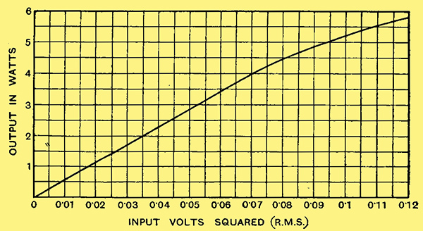
Fig, 1. - This curve shows the relationship between the square of the input voltage to the amplifier and the power output. It is a straight line for outputs up to 4 Watts, indicating distortionless amplification. The distortion at 6 Watts, however, is quite small.
The degree of linearity obtainable by following the procedure laid down in this article is well brought out by the curves of Figs. 1 and 2. Fig. 1 shows the relationship between the square of the input voltage and the power output of an amplifier, full details of which are given here. It is a straight line up to the maximum output of 4 Watts, but after this the overload point is reached.
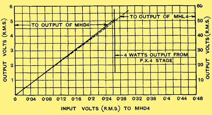
Fig. 2. - One curve indicates the input output characteristics of the first amplifier stage, while the other gives the same information for the first two stages together. Both curves are straight lines for inputs below 0.265 Volt RMS.
Fig. 2 shows the linearity of the individual stages, one curve showing the relationship between input and output volts for the first triode, which has a load impedance of 100,000Ω, and the other the relationship between the input to the amplifier and the input to the output stage. Both curves are straight for inputs exceeding that for 4 Watts output, showing that the non-linearity of the whole amplifier at outputs over 4 Watts is due entirely to the output stage, as it should be.
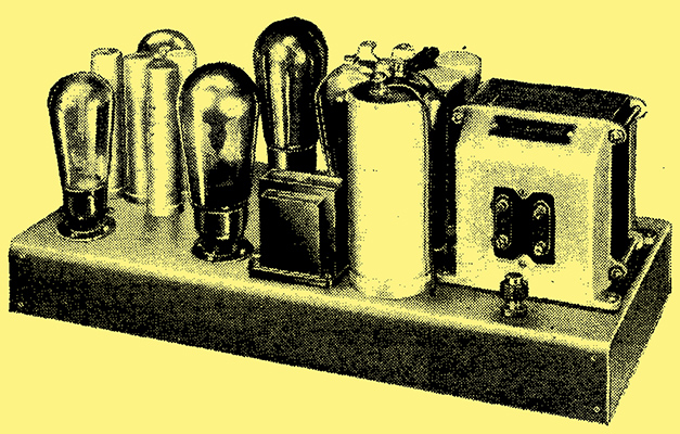
A high quality amplifier with two push-pull stages.
|