|
The methods which can be employed for feeding a push-pull amplifier are many and various, and the correct arrangement depends upon the type of receiver which is used. Some of the more important feeder systems which may be used with The Wireless World Push-Pull Quality Amplifier are described in this article, and it is shown that the method to be adopted depends very largely upon whether a straight or superheterodyne receiver is employed.
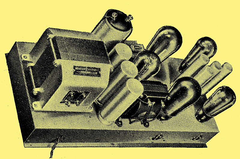
The Wireless World Push-Pull Quality Amplifier.
That apparatus designed primarily for high-quality reproduction is appreciated by the discriminating listener has been amply demonstrated by the reception of The Wireless WorldPush-Pull Quality Amplifier [★] The Wireless World, May 11 and 18, 1934 - See extras menu for details. Correspondence has shown, however, that some doubt exists as to the best method of coupling it with an existing receiver. Some notes on this matter were given in the constructional articles, but were necessarily confined to a few cases.
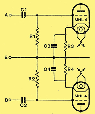
Fig. 1. - The input circuit of the Push-Pull Quality Amplifier.
The input connections of the amplifier are shown in Fig. 1, and about 5.07 Volts RMS, or 7.17 Volts peak, must be maintained across the input terminals for an output of 4 Watts. This input must be so split that one-half of it (3.585 Volts) appears between AE and one-half between BE. Moreover, the voltage across must be 180 degrees out of phase with that across BE.
The simplest input system is undoubtedly a push-pull transformer with its two outer secondary terminals connected to A and B and its centre-tap to E. In order to preserve the transformer characteristics, of course, C1 and C2 should be short-circuited, and R1 and R2 removed from the amplifier. The primary of such a transformer is naturally connected in accordance with standard practice.
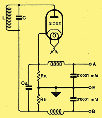
Fig. 2. - The amplifier may be fed directly from a diode in the manner shown in this diagram.
Many feel, however, that the full benefit of the amplifier is not obtained if a transformer be included, and prefer to adhere to resistance coupling throughout. The simplest coupling is then undoubtedly a direct feed from a diode detector, as shown in Fig. 2. The resistances Ra and Rb should each be of 50,000Ω, and Ca can be 0.0001 μF, the output terminals, of course, are connected to the correspondingly lettered input terminals of the amplifier.
Direct Diode Feed
The modulated input appearing across the circuit LC is applied between the diode anode and cathode in the usual way through the bypass capacitor Ca. Rectification occurs in the diode and modulation frequency currents flow through Ra and Rb exactly as with the usual diode detector. Since the current through Ra is the same as that through Rb, and the two resistances are of equal value, it follows that the potentials developed across them have the same value. Now consider the question of phase. Suppose that A is positive with respect to B at a given instant, then E is also positive with respect to B, and A is positive with respect to E. If E is more positive than B, however, B must be negative with respect to E. We thus find that the points A and B are always of equal and opposite potential with respect to E, and so the system is suitable for feeding a push-pull stage.
One of the greatest disadvantages of this system is that volume control must normally take place before the detector, and if gramophone reproduction be required, a separate feeder stage is necessary for this. It has been said that the total amplifier input required for 4 Watts output is 7.17 Volts peak, and if this is to be obtained with 80% modulation, the detector input must be about 13 volts peak if an MHL4 valve with grid and anode strapped be used for the diode. If the two diode anodes of a duo-diode-triode be used; the input required will be about 15 Volts peak. In either case, detection should be almost completely distortionless. An input of this order can rarely be obtained, even from a local station, Without an stage, and for more than purely local reception two stages should be provided.
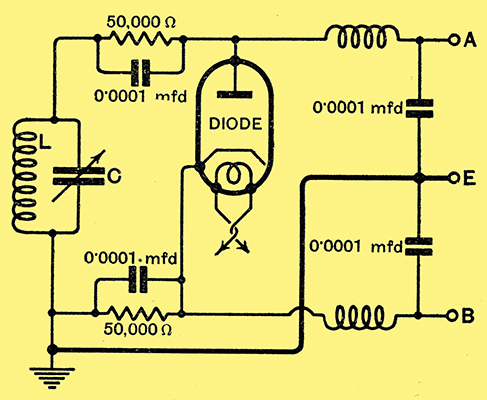
Fig. 3. - An alternative method of using a diode for feeding the amplifier when the tuned circuit must be earthed.
One disadvantage of the circuit of Fig. 2 is that neither terminal of the tuned circuit can be earthed, but this may be overcome by rearranging the connections on the lines shown in Fig. 3. The tuned circuit can then be of any conventional type such as an HF transformer or the tuned grid circuit.
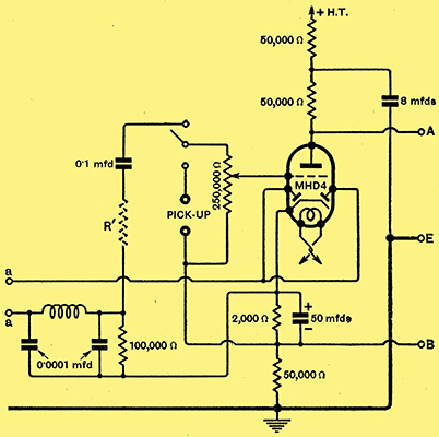
Fig. 4. - A duo-diode-triode can be employed to provide both detection and amplification by using the arrangement shown in this diagram. The HF input circuit is connected to the points (aa).
A more generally useful arrangement is shown in Fig. 4, and it will be observed that the triode section of the duo-diode-triode valve is connected in the same way as the triode in the feeder unit described for the Push-Pull Quality Amplifier. In this case the push-pull output is obtained with the aid of a triode, and the mechanism is the same on both radio and gramophone. The operation can best be seen from the simplified diagrams of Fig. 5, and the complete triode circuit is shown at (a). Now the impedance of Ca and Rd in parallel is negligible at the operating frequencies, and the reactance of Cb is also negligibly small, While Rc is very high. As regards LF, therefore, We can replace Fig. 5a by Fig. 5b, and it will be seen that as in the diode circuit the output is taken across two series connected resistances of equal value, the mid-point of which is earthed. The operation, therefore, is identical, and the differences in the practical circuit are only those occasioned by the necessity for providing the correct steady operating potentials on the valve.
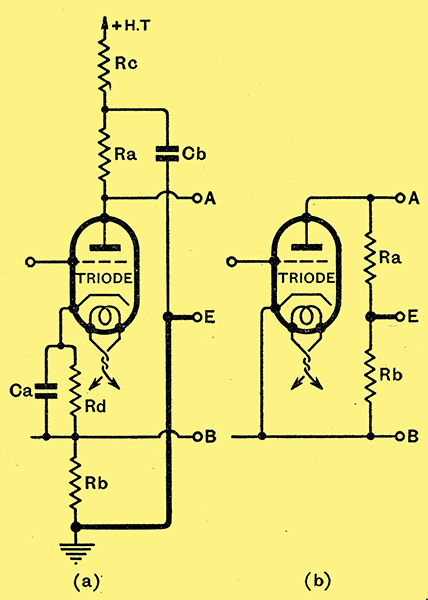
Fig. 5. - The fundamental connections of the triode portion of the valve in Fig. 4 are shown at (a), while (b) illustrates how the phase reversal is obtained.
Using a Duo-diode-triode
In Fig. 4 rectification occurs in the diode circuit, and the resulting LF potentials are passed to the triode through a resistance-capacity coupling. Since there is an additional stage of amplification, the detector input is now much less, for it has to provide an output of only 0.36 Volt peak on an 80% modulated carrier. When giving such a small output a diode detector is by no means distortionless, so in the interests of quality it is necessary to provide the detector with a larger input and to throw away a portion of the output.
Recent work on diode detectors has shown that when the MHD4 valve is used with the two diode anodes connected together, and with a load resistance of 1O0,000Ω, the input can be as small as 2 Volts peak without distortion becoming appreciable. It is, in fact, only about 0.25% for 80% modulation, and is even less for larger inputs. It has previously been thought that the input should be of the order of 10 Volts, but it now appears that this figure is unnecessarily high. It should not be forgotten, however, that diodes vary in their characteristics, and a valve of a different make may require a larger input.
With a 2 Volts detector input, the output is 1 Volt peak for 80% modulation, and the triode portion of the valve requires 0.36 Volt. Since we must throw away a portion of the detector output by means of some form of potentiometer, it is convenient to adopt a round figure for the ratio of detector output to amplifier input, for this will lead to standard values of components. Let this ratio be 3:1, obtained by the insertion of the 500,000Ω resistance R' (dotted in Fig. 4). The detector output required is then 0.36 × 3 = 1.08 Volts peak, and will be obtained with an 80% modulated carrier of 2.15 Volts peak, or 1.52 Volts RMS between the points (aa) of Fig. 4.
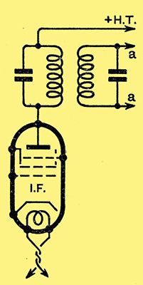
Fig. 6. - The last IF coupling in a superheterodyne usually takes the form shown here and it may precede the valve of Fig. 4 by joining the points (aa) on the two diagrams.
The voltage at (aa) must be produced across some type of HF circuit, and it is here that most difficulty arises, for neither terminal may be earthed. In the case of a superheterodyne the matter is easily arranged, and the circuit of the preceding stage can take the form shown in Fig. 6. There is also no difficulty in a single-span receiver and details of the connections were given in The Wireless World for June 22, 1934. With a straight set the solution is not so straightforward, because in these days of ganged tuning one side of the variable capacitor must be earthed. The difficulty can be got over by adopting the arrangement of Fig. 7.
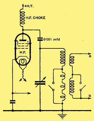
Fig. 7. - In the case of a straight set the feeder system of Fig. 4 is best preceded by a transformer coupling as shown in this diagram.
It will be seen that an HF transformer is employed, but the normal primary winding is used to feed the diode detector, and the tuned circuit is fed from the HF valve by means of an HF choke and a capacitor. For maximum efficiency, the transformer ratio should not be greater than some 2:1, but quite good results can be secured with a ratio as high as 3:1. With none of these systems, of course, is it possible to employ reaction satisfactorily.
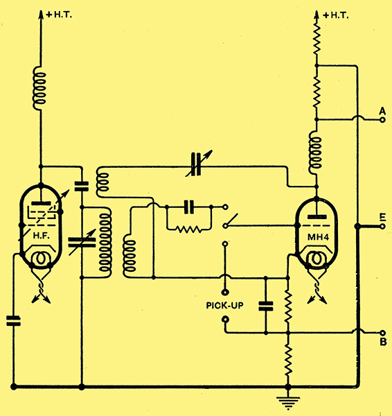
Fig. 8. - It is possible to employ a power grid detector to feed the amplifier, and this is the best arrangement if reaction be required.
Although the duo-diode-triode lends itself best to feeding a push-pull amplifier, it is quite possible to use a grid detector and reaction can then be embodied. The connections of such an arrangement are shown in Fig. 8 which is self-explanatory. Apart from the ability to obtain reaction, this system ha s no advantage over the recommended method embodying a duo-diode-triode, and it is indeed inferior to it in certain respects.
The use of the amplifier on gramophone is quite straightforward and has already been fully dealt with, but it is sometimes desired to employ a microphone. Essentially this is no different from a pick-up, and it is only necessary to connect the secondary of the microphone transformer to-the pick-up terminals. Most good quality micro-phones are designed to operate into an impedance of 500Ω, and the resistance of the volume control is 250,000Ω. In general, therefore, the transformer should have a ratio of 1:22.4.
Using a Microphone
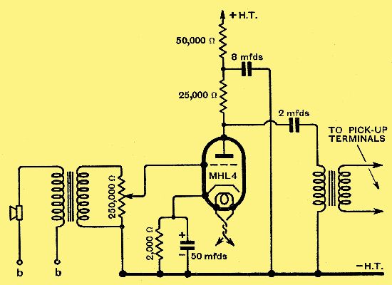
Fig. 9. - If an insensitive microphone be employed an additional stage of amplification is advisable.
The only difficulty which may be experienced is in obtaining sufficient volume, for most good quality microphones give only a small output, perhaps 0.1 Volt or less, while the input required by the amplifier is about 0.36 Volt peak. The only remedy, of course, is to increase the amplification, and there is no doubt that this is best done by including another stage of push-pull amplification between the feeder valve and the amplifier proper. A pair of MHL4 valves with the same connections and circuit values as those in the amplifier should function admirably. This arrangement is hardly worth while, of course, unless the equipment is to be used chiefly with a microphone, for on radio and gramophone the amplification would be unnecessarily large.
In general, therefore, the arrangement of Fig. 9 is best adopted for microphone working. The LF transformer should be of low ratio, about , 1:1 so that excessive amplification is not obtained, and a good frequency response is secured with the pick-up volume control connected across its secondary. The necessary current for operating the microphone can be secured by connecting a battery to the points (bb), or it may be obtained by closing these points by a resistance, shunted by a 50 μF electrolytic capacitor, which is included in the main negative HT return lead of the amplifier. The value of the resistance, of course, will depend upon the current and voltage requirements of the microphone, and so will vary according to the component selected.
|