|
A Survey of Developments over Three Decades
Until the year 1928 the cathode-ray tube devised in 1897 by Ferdinand Braun only found application on rare occasions, despite the fact that Wehnelt (in 1905) and Westphal (in 1908) had already improved it considerably by the introduction of the incandescent cathode. In 1928 the cathode-ray tube emerged from its latent existence and rapidly gained in importance in two directions of development:
- About this time the high-tension cathode-ray oscillograph with cold cathode and continuous evacuation made its appearance for the investigation of transient waves. The development of this instrument is linked with the names of Rogowski, Gabor, Dufour, MacGregor-Morris, von Borries and Binder.
- The cathode-ray tube of modern design, which today plays important roles in the fields of oscillography, radar, and television, made its appearance.
A kindly fate has made it possible for me to collaborate actively in this second direction of development over a period of more than three decades. Today, perhaps, I may be permitted to look back over the field of my personal experience in this work.
Looking Back
The development of the modern cathode-ray tube received a decisive impetus in 1928 when it became possible, in my laboratory at Lichterfelde, to produce a fine electron beam with a current density of about 100μA and an acceleration of up to 3,000 Volts as a result of a three-electrode system with a hot cathode and a control electrode with a negative bias. This electron gun was not only characterised by its construction from a thermal small-area cathode, a control electrode with negative bias and an anode, as well as by the geometry employed. Its most significant feature was the formation of an electron beam cross-over of small cross-sectional area and high current density. This emitting system differed from all earlier methods of operation of similar electrode arrangements in that the negative bias of the control electrode had a definite value somewhat below the initial voltage of the cathode-ray current. So far as can be seen from the literature available, these features were combined for the first time in the oscillograph tube [1] NN. Neuer Gluhkathoden-Oszillograph. Mitteilungen der E Leybolds Nachfolger A G Koln. December 1929. developed by me in 1928 and put on the market in 1929 by E Leybolds Nachfolger of Cologne.
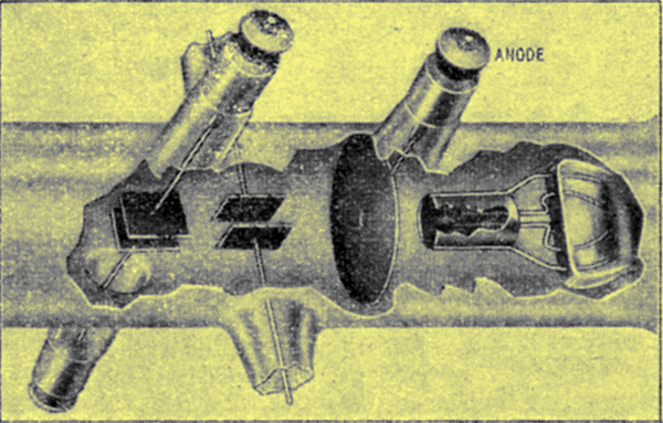
Fig. 1. The electron gun developed in I928 with negatively-biased control electrode and beam cross-over. This gun, which is used in most present-day electron beam appliances, is shown here in an oscillograph tube for anode voltages above 1kV, introduced by Leybold of Cologne in I929.
Fig. 1 shows the structure of this tube with the type of electron gun characterised by the cross-over formation, as is used today in a great many electron devices. Another branch of oscillograph technology which was making strides at that time, and which was later to achieve great significance in television engineering, radar engineering and high-frequency carrier telecommunications, was the wide-band amplifier or, as we called it in those days, the 'aperiodic high-frequency amplifier'. Together with Siegmund Loewe, we had begun in 1925 to combine several valve systems with their low-capacitance coupling units in a single evacuated glass envelope. In this way the Loewe dual valve, shown in Fig. 2, which had a space-charge grid system with a steep slope, was able to achieve a bandwidth of 1 MHz [2] M von Ardenne und S Loewe, Zweisystemrohren fur Hochund Niederfrequenzverstarkung. Jahrbuch d. drahtl. Telegraphic u. Telephonie 27, 19, 1926. M von Ardenne, Die aperiodische Verstarkung von Rundfunkwellen, Z Hochfrequenztechn. 33, 166, 1929..
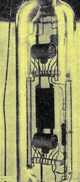
Fig. 2. The Loewe dual tube, developed in 1925, was in fact the first wide-band amplifier, in the modern sense of the term, and had a bandwidth of 1 MHz. This was obtained by the combination of a particularly low-capacitance circuit with high-slope valve systems.
In order to change over from timebase deflection by mechanical/optical means (rotating mirror) to deflection by low-inertia electrical methods, relaxation oscillator devices were devised in that particular year in the Lichterfelde laboratory, on the basis of publications by B van der Pol and H Fruhauf with the collaboration of I Kammerloher. These gave triangular waveforms which could be synchronised by means of a cold-cathode thyraton with external control from the signal [3] B van de Pol, uber Relaxationsschwingungen. Z Hochfrequenztechn. 25, 121, 1925. H Fruhauf, Neue Schaltung zur Erzeugung von Schwingungen mit linearem Spannungsverlauf Arch. Elektrotechn. 21, 471, 1929..
In the year 1930 there were available, in my laboratory in Lichterfelde, electron beam tubes with intensity modulation electrodes and high focal point brightness [4] M von Ardenne, Die Braunsche Rohre als Fernse- hempfanger. Fernsehen. 1, 193, 1930., relaxation oscillator devices to suit these and wide-band amplifiers in large numbers ready for operation. At that moment it was only a short step to the realisation of television on a purely electronic basis. The technical prerequisites for this purpose were so favourable as a result of the fact that the three basic elements were standing ready in one building, that this realisation, from the time of making the decision to the time of succeeding in an experiment, required hardly more than one days wiring operations and experimental effort.
The stimulus for starting this work came in the main from outside. Since 1924 I had been following with great interest the reports of the pioneer experiments by J L Baird in England using mechanical scanning of the picture by means of a Nipkow disc [5] Dinsdale, First Principles of Television. Chapman & Hall, London, 1932.. This interest was considerably increased when D von Mihaly demonstrated practical experiments at the Berlin Radio Exhibition of 1928, using an arrangement which was somewhat similar to a Baird televisor, and the demonstrations of mechanical television continued at the Radio Exhibitions of 1929 and 1930 with increasing quality. Finally, I received a particularly powerful stimulus to carry out this work from the experience of a personal meeting with Baird himself, and from the detailed discussions with him regarding the limits of the mechanical methods employed at that time.
Despite repeated indications of the advantages of the electronic method by Fritz Schroter and myself, in lectures and articles, television experiments continued to be conducted with mechanical scanning only. The time had become ripe for some experiments of our own. These experiments led to the achievement, on the 14th of December, 1930, of the first television pictures obtained on a purely electronic basis. One of the pictures, obtained in the year 1930, is shown in Fig. 3(a). A few months later the quality of the pictures had already been increased to the stage shown in Fig. 3(b).
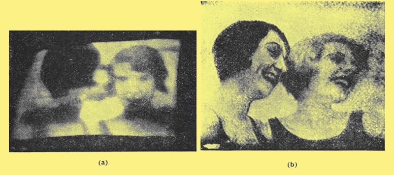
Electron beam television pictures produced (a) in the year 1930 and (b) in 1931.
An important factor in carrying out the television transmission experiment so quickly with electron ray tubes both at the transmitter and at the receiver, was the conception of the flying spot scanner [6] M von Ardenne, Uber neue Fernsehsender und Fernsehempfanger mit Kathodenstrahlrohren, Fernsehen. 2, 65, 1931.. Since then the flying spot scanner has been further developed for the scanning of colour films, for facsimile transmission of over 1 million words per minute (Ultra-fax), for counting and sorting of particles on microscope slides, for optical auto-correlation measurements and many other purposes. As is known, this scanner works by deflecting a light spot over the screen of a cathode-ray tube with short after-glow so as to produce a bright raster which is focused by an object lens on the slide or film to be transmitted. The beam of light passing through the slide or film is then fed to a photoelectric cell. According to the optical density of the picture points encountered by the scanning spot a greater or lesser quantity of light is absorbed, so that the electron current emitted by the photoelectric cell is proportional to the brightness values of the picture points.
Soon after the first experiments with slides, the device used at that time was converted for the scanning of cinematographic films. The first public demonstration of the equipment as a whole was made in the autumn of 1931 at the Berlin Radio Exhibition. It had already been demonstrated to most of the leading technicians of the various European development centres. Because of the simplicity of the arrangement and the brightness of the pictures obtained, these demonstrations turned out to be such effective propaganda for the electronic method that, one year later at the Radio Exhibition of 1932, television receivers with cathode-ray tubes were exhibited by several radio firms. Today I still regard one of the great events of those days to be a visit to the Lichterfelde laboratory, of J L Baird, who unfortunately is no longer with us (see Fig. 4).
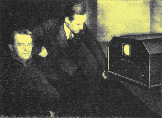
The British television pioneer J L Baird (left) on a visit to our television laboratory in Berlin-Lichterfelde.
During these demonstrations there had already been a display of the projection of television pictures from a cathode-ray tube on to a large screen of about 1 square metre, using a special optical system [6] M von Ardenne, Uber neue Fernsehsender und Fernsehempfanger mit Kathodenstrahlrohren, Fernsehen. 2, 65, 1931..
In the efforts to increase still further the brightness of the picture, and to increase the number of picture elements which could be transmitted for a given frequency band of the transmission channel, experiments were carried out in the Lichterfelde laboratory in 1932, partly with the collaboration of Kurt Schlesinger, using the so-called 'variable speed scanning method' proposed shortly before by Richard Thun [7] M von Ardenne, Die praktische Durchfuhrung der Thunschen Liniensteuerung unter Anwendung neu entwickelter Methoden, Fernsehen. 3, 210, 1932.. As is known, in this method the control of the brightness of the picture elements is effected by changing the speed of deflection of the light spot, so that at the receiving end the picture is reproduced always with the maximum possible spot brightness. Against this, in the modern television method only a mean spot brightness is effective.
In view of the advantages offered by the variable speed scanning process it is surprising that, up to the present time, nobody has tried out this process in industrial television, where there are no television standards which have to be observed. At that time, in 1932, our efforts with a system of television picture reproduction using variable speed scanning very soon found powerful support in the London laboratories of Cossor in the work of Bedford and Puckle [8] L H Bedford and O S Puckle, A Velocity-modulation television system, Journ. IEE 75, 71, 1934.. These workers improved the quality of the picture by controlling the brightness not only by varying the line deflection speed, but also by using a certain amount of intensity control of the light spot.
In the year 1933 the demand for electron ray tubes began to increase at a tremendous rate. One of the largest customers in those days was the development centre at Slough in charge of R A (now Sir Robert) Watson-Watt, which often required deliveries of from 50 to 100 cathode-ray tubes. At the same time there arose an ever-increasing demand for the construction of complete cathode-ray oscillographs with built-in power packs and timebase units. It could be foreseen that the production possibilities of our small Lichterfelde laboratory would rapidly be exhausted. For this reason, working in collaboration with Leybold, the 'Leybold-von Ardenne-Oszillo-graphen-Gesellschaft' was founded which grew extremely rapidly in the years which followed. Even this company was no longer able to cope with the tremendous increase in the requirement for oscillographs, and shortly before the outbreak of the second world war it was taken over by the firm of Siemens and Halske of Berlin.
As a result of the development in Lichterfelde, the Leybold-von Ardenne company brought out the polar co-ordinate electron beam oscillograph in the year 1936 [9] M von Ardenne, Ein neuer Polar-Koordinaten- Elektronenstrahl-Oszillograph mit linearem Zeitmasstab, Z. techn. Physik. 17, 660, 1936.. In this apparatus, which made use of some of the radar techniques being introduced at that time, the timebase was described by an exactly circular movement of the light spot and the measuring deflection was carried out in a radial direction.
Already the transition from the gas-filled to the high-vacuum cathode-ray tube with beam concentration by electron-optical methods had been completed. Already, in the television tubes of 1930 and 1931, electrode arrangements had been used in the Lichterfelde laboratory which are known today as electrostatic focusing lenses, and the control knob on the receiver for adjusting the voltage to these lenses was marked 'Focusing'. Based on the work of Busch [10] H Busch, Uber die Wirkungweise der Konzentrationsspule bei der Braunschen Rohre, Arch. Elektrotechn. 18, 583, 1927., the electron-optical mode of operation had been developed by Calbrick-Davisson, Briiche, Knoll, Recknagel, Scherzer and others [11] Vkl E Bruche und A Recknagel, Elektronengerate, Springer, Berlin, 1941.. It was therefore soon possible in Lichterfelde, with comparatively few stages of experimentation, to develop high-vacuum cathode-ray tubes with a long cathode life and with anode voltages of up to more than 8 kV for mass production [12] M von Ardenne, Beitrag zur Konstruktion von Braunschen Rohren mit Hochvakuum fur Fernseh- und Messzwecke. Z Hochfrequenztechn. u. Elektroak. 44, 166, 1934..
A parallel idea to my electron raster microscope came into being in 1938 in the form of the closely related electron-optical ray path of the electron micro-oscillograph [13] M von Ardenne, Der Elektronen-Mikrooszillograph, Z. Hochfrequenztechn. u. Elektroak. 54, 181, 1939. M von Ardenne, Ein Sechsfach-Elektronen-Mikroos-zillograph. Z. Hochfrequenztechn. u. Elektroak. 58, 156, 1941.. In this type of oscillograph, which was developed for Siemens with three or four scanning systems, the scanning spot was focused by means of a magnetic lens with a short focal length and a comparatively large beam aperture. In this way a scanning spot having a diameter of only about 10 microns was obtained, which gave an extraordinarily high current density at the anode voltage of 50 kV. This feature made it possible for the oscillograph to have an unusually high scanning speed. Since the deflection plates were also produced in 'micro' construction and consequently the transit time effects were reduced, the instrument opened up possibilities of oscillographical investigation of transient phenomena at very high frequencies. This oscillograph principle has become known particularly through the Lee [14] G M Lee, A three-beam oscillograph for recording at frequencies up to 10,000 megacycles, Proc. IRE 34, 121, 1946. equipment in Fig 5.
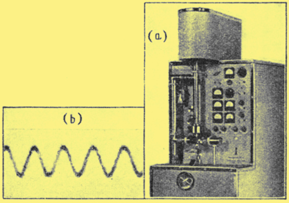
(a) The electron micro-oscillograph devised in I939 became well known, particularly through the equipment developed by Lee shown here. At (b) is a 'one-shot' oscillogram of a wave with a frequency of 3,000 MHz, traced with a 10-micron scanning spot.
Very often certain inventive ideas occur quite independently of one another, and almost simultaneously, when the time for their conception is ripe. As an example of this I would like to recount here an incident from the early part of the second world war. H E Hollmann, a radio physicist also working in Lichterfelde, and I had decided in 1940 to work jointly on the development of a panoramic radar apparatus with decimetric waves [15] Vgl. hierzu die Bemerkung in M von Ardenne. Tabellen der Elektronenphysik, Ionenphysik und Ubermikroskopie Bd. I. Deutscher Verlag der Wissenschaften, Berlin, 19, 1956.. The basic concept was already pretty obvious to us as a result of the polar co-ordinate oscillograph I have already mentioned. We foresaw the tremendous importance of the panoramic radar principle for the future, and so the development proposal was taken direct to the German government minister, Goering, who was at that time responsible for aviation research. Goerings answer, that the war was already won and consequently there was no longer any need for a development which would not bear fruit for one or two years, characterizes the mental capacity of the system of government ruling in Germany at that time. Approximately at the same time as ourselves, Watson-Watt had begun the development of his panoramic radar system which found its way into the history of the second world war and, encouraged by the farsightedness of his Government, was brought to such a successful conclusion during the years which followed.
At the end of the war, the Lichterfelde laboratory, which had remained completely intact, was transferred, together with its staff, to the south of the Soviet Union. Here, in 1952, was the first opportunity for re-commencing our work in the field of electron beam devices. The result was the precision electron beam oscillograph with a scanning spot of about 3 microns diameter and a scanning area of almost 9 ×12 centimetres.
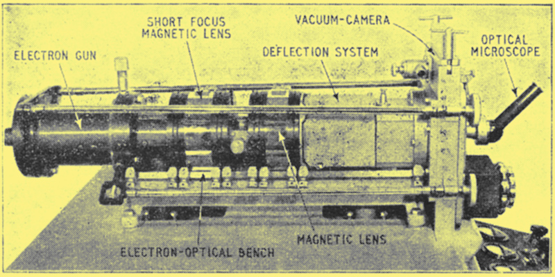
Layout of the precision electron beam oscillograph developed during the period I952-55. In this apparatus, built by VEB Vakutronik of Dresden, the scanning spot is only 3 to 5 microns and the scanning area is about 9 cm x I2 cm.
Fig. 6 shows the apparatus [16] M von Ardenne, Ein Prazisions-Elektronenstrahlos- zillograph mit wenigen u Schreibfleckdurchmesser. Nachrichtentechn. 5, 481, 1955. which was further perfected after the return to Dresden from the Soviet Union. The fine focusing of the scanning spot was carried out with the help of a grainless luminous screen, which was observed through an optical microscope. The photograph in the vacuum camera is taken on a 9cm × 12cm photographic plate with a fine-grain thin emulsion layer.
This oscillograph differs from the micro-oscillograph mentioned earlier in respect of the increased length of the deflected beam and the extreme sharpness of the spot. By virtue of the large deflected beam length and the extremely small convergence angle of the writing beam, the deflection errors with this system are reduced to the extent that nearly 109 image points can be accommodated on an oscillograph screen of the size mentioned. This figure is about four orders of magnitude higher than in the case of the usual cathode-ray oscillograph. Consequently, as a result of the smallness of the beam convergence angle (2αl ≈ 3 × 10⁻⁴), the photographic scanning speed of this type of oscillograph (as also the scanning speed in relation to the diameter of the scanning spot) is necessarily small. Furthermore, as a result of the smallness of the scanning spot the oscillograms are not visible to the naked eye, so that in order to observe them it is necessary to use an optical microscope.
By means of this type of oscillograph, which is only at the beginning of its applications in research work, the fine structure of oscillograms is opened up to direct observation. Two sections of an oscillogram obtained with this apparatus, one highly magnified and the other very highly magnified, are shown in Fig. 7.
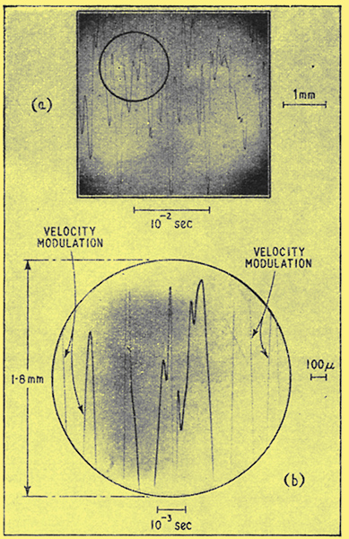
Highly-magnified sections from a precision oscilogram of a music waveform at the output of a radio receiver: (a), section magnified 15 times (approx. 1/900 of the area of the 9 cm x 12 cm photographic plate); (b), section magnified 56 times, showing velocity modulation of the scanning line by residual IF signal from the receiver. (Approx. 1/4000 of the surface area of the 9 cm x l2 cm photographic plate!).
These will perhaps serve to give an idea of the properties of this latest child of the electron beam oscillograph family. By recording the fine structure of characteristics in plasma investigations (characterizing the stability of the plasma), by making visible details of curves produced by the Barkhausen effect, by plotting fine details of transistor characteristics, the precision electron beam oscillograph has already introduced a new era in the graphical recording of electrical phenomena. The first results of this type of oscillographic recording have already shown great promise, particularly in studying the fine structure of electro-encephalograms, electro-cardiograms and nerve action potentials.
Looking Forward
It is perhaps a comforting thought for the younger generation that there are still many important problems in the science and technology of electron beam devices which remain to be solved in the future. Some of these problems can be clearly seen already, or are delaying the introduction of apparatus into practical use. Perhaps I may be permitted to conclude this article with a few remarks regarding such fields which so far have hardly been broached.
As far back as 1955 H E Kallmann [17] H Kallman, Beam-hugging plates for unlimited cathode ray deflection. Proc. IRE 43, 485, 1955. had mentioned a new deflection system by means of which the deflection sensitivity in the Y direction can be increased by about one order of magnitude. It is worthy of note that this system has found no application up to the present. A start was made at testing it out in conjunction with the precision electron beam oscillograph, because the new deflection principle could be a great step forward in this technique, where there is a very small beam cross-section in the deflection space. The relative deflection sensitivity of the precision oscillograph in terms of the diameter of the scanning spot is already more than one order of magnitude higher than that of the cathode-ray oscillograph tubes available on the market. One should therefore expect that this combination, at present in the development stage, should provide a total increase of more than two orders of magnitude of Y deflection sensitivity.
With very many measuring problems this advance would make it possible to manage completely without a deflection amplifier. This prospect is particularly valuable in the case of the precision oscillograph, because the fine structure of the oscillogram would no longer be restricted by fluctuations in the deflection amplifier, and only the fine structure of the waveform under investigation would be made visible.
Closely related to the questions I have just touched upon is another line of development, in which low-noise amplifiers are used as deflection voltage amplifiers for oscillographs, especially for precision instruments. The future use of low-noise amplifiers in conjunction with precision oscillographs, for example, in the field of action-potential oscillography in medicine and physiology (observing the details of electro-cardiograms, electro-encephalograms and so on) should lead to interesting results. Some of the tasks which face the precision oscillograph today will perhaps also be carried out by means of a special oscillograph tube with a very high spot sharpness (e.g. 5 to 10 microns), equipped with a suitable electron lens, with a grainless cemented luminous screen and with an anode voltage of 10 to 30 kV.
A wide field of application, especially in the field of medical electronics, should be claimed by the single-gun multiple oscillograph with television tube bulb, of which individual examples have already been constructed. With this 4 to 6 waveforms can be traced simultaneously on an after-glow screen with the help of an electronic switch.
Far greater efforts will be made than in the past to achieve the direct recording of oscillograms in single processes. Going beyond the recording tubes which have already been developed so far there should be wide use in practice for tubes with the facility of storing traces and also for instruments with xerographic recording of oscillograms developed from the old idea of Selenyi [18] P Silenyi, Methoden, Ergebnisse und Aussichten des elektrostatischen Aufzeichnungsverfahrens. Z. techn. Physik. 16, 607, 1935..
References
- NN. Neuer Gluhkathoden-Oszillograph. Mitteilungen der E Leybolds Nachfolger A G Koln. December 1929.
- M von Ardenne und S Loewe, Zweisystemrohren fur Hochund Niederfrequenzverstarkung. Jahrbuch d. drahtl. Telegraphic u. Telephonie 27, 19, 1926. M von Ardenne, Die aperiodische Verstarkung von Rundfunkwellen, Z Hochfrequenztechn. 33, 166, 1929.
- B van de Pol, uber Relaxationsschwingungen. Z Hochfrequenztechn. 25, 121, 1925. H Fruhauf, Neue Schaltung zur Erzeugung von Schwingungen mit linearem Spannungsverlauf Arch. Elektrotechn. 21, 471, 1929.
- M von Ardenne, Die Braunsche Rohre als Fernse- hempfanger. Fernsehen. 1, 193, 1930.
- Dinsdale, First Principles of Television. Chapman & Hall, London, 1932.
- M von Ardenne, Uber neue Fernsehsender und Fernsehempfanger mit Kathodenstrahlrohren, Fernsehen. 2, 65, 1931.
- M von Ardenne, Die praktische Durchfuhrung der Thunschen Liniensteuerung unter Anwendung neu entwickelter Methoden, Fernsehen. 3, 210, 1932.
- L H Bedford and O S Puckle, A Velocity-modulation television system, Journ. IEE 75, 71, 1934.
- M von Ardenne, Ein neuer Polar-Koordinaten- Elektronenstrahl-Oszillograph mit linearem Zeitmasstab, Z. techn. Physik. 17, 660, 1936.
- H Busch, Uber die Wirkungweise der Konzentrationsspule bei der Braunschen Rohre, Arch. Elektrotechn. 18, 583, 1927.
- Vkl E Bruche und A Recknagel, Elektronengerate, Springer, Berlin, 1941.
- M von Ardenne, Beitrag zur Konstruktion von Braunschen Rohren mit Hochvakuum fur Fernseh- und Messzwecke. Z Hochfrequenztechn. u. Elektroak. 44, 166, 1934.
- M von Ardenne, Der Elektronen-Mikrooszillograph, Z. Hochfrequenztechn. u. Elektroak. 54, 181, 1939. M von Ardenne, Ein Sechsfach-Elektronen-Mikroos-zillograph. Z. Hochfrequenztechn. u. Elektroak. 58, 156, 1941.
- G M Lee, A three-beam oscillograph for recording at frequencies up to 10,000 megacycles, Proc. IRE 34, 121, 1946.
- Vgl. hierzu die Bemerkung in M von Ardenne. Tabellen der Elektronenphysik, Ionenphysik und Ubermikroskopie Bd. I. Deutscher Verlag der Wissenschaften, Berlin, 19, 1956.
- M von Ardenne, Ein Prazisions-Elektronenstrahlos- zillograph mit wenigen u Schreibfleckdurchmesser. Nachrichtentechn. 5, 481, 1955.
- H Kallman, Beam-hugging plates for unlimited cathode ray deflection. Proc. IRE 43, 485, 1955.
- P Silenyi, Methoden, Ergebnisse und Aussichten des elektrostatischen Aufzeichnungsverfahrens. Z. techn. Physik. 16, 607, 1935.
|