|
The cathode-ray oscillograph is becoming more and more important in its applications to investigating what happens in wireless circuits, and particularly in indicating wave form and distortion. One of the most important applications of the cathode ray tube is, however, its use in television systems. The purpose of the present article is to give the reader a clear idea of the principle of operation of the tube, in order to pare the way for a better understanding of television circuits where the tube is employed.
What It Is and How It Works
When receiving an ordinary wireless signal the valves in the receiver have to deal with currents that may change their direction several million times in a second. Between each reversal of direction and the next, there is a continual variation in the intensity of the current, and the valve is called upon, if it is to amplify without distortion, to follow even this finer detail of an immensely rapid phenomenon.
The current is carried through the valve by electrons, which are particles of more or less material type flying, under the influence of the various voltages applied to the electrodes, through the evacuated space. The inconceivable rapidity of their response to the fluctuations of the voltages applied is a graphic demonstration of their extreme smallness and almost complete lack of inertia.
In the valve, although the flying electrons respond to the fluctuations of voltage on the grid, there is no satisfactory means of observing this response. The only way in which the variations of current can be made visible is by connecting a milliammeter in series with the valve, and though the milliammeter will indicate faithfully enough any slow changes in current, the mechanical inertia of its moving parts (coil, pointer, and so forth) make it quite impossible for it to follow changes in currents which are varying at any really high speed. By choosing a mechanical indicating instrument we lose, in fact, all the advantages that the instant response of the electrons seemed to offer.
The cathode-ray oscillograph is, in essence, a type of valve in which the electrons are themselves made visible, so that their movements, no matter how rapid they may be, can be followed by the eye. Though the electrons are far too small to be seen, individually or in groups, the energy they carry, especially when travelling really fast, is fairly considerable. A thin beam of electrons, arriving at a point with a velocity acquired by being made to pass through a thousand Volt field, carries power equivalent in magnitude to that dissipated by a glow-worm or other faint but readily visible light-source.
Conversion into Light
The problem of converting the electromechanical energy of the flying electrons into light, in order that their energy may be directly appreciated by the senses, is solved by the fluorescent screen. This consists of a thin layer of suitably prepared calcium tungstate or zinc silicate coated upon glass or other support. When a beam of high-velocity electrons strikes such a screen, the electrons are stopped and the energy of the flight is largely converted into light. The arrival of the electrons is thus made visible by the appearance of a glow upon the screen, the size and shape of the glow corresponding to the area upon which the electrons are impinging.
In a valve, variations in the voltages applied to the control-electrode (the grid) are represented in the anode circuit by variations in current - that is, by variations in the number of electrons arriving at the anode in each second. Such variations, if made visible with the aid of a fluorescent screen, would show up as fluctuations in brilliance of the patch of light a type of change to which the eye is extremely insensitive. The construction of an electron-tube designed to enable rapidly varying voltages to be studied by visual examination must, therefore, be different from that of a valve, the design being directed towards deflecting the electrons in their flight in a manner depending upon the voltage instead of varying the number of them passing through the tube. By this means the changes in the voltage to be studied are seen as movements of a point of light across the fluorescent screen.
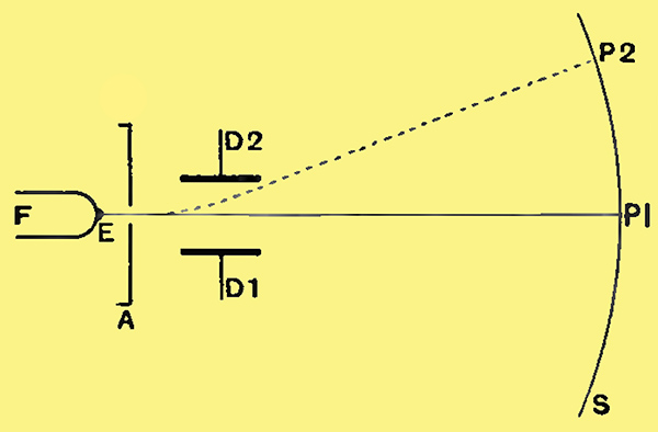
Fig. 1. - Electrodes and screen of a crude oscillograph tube, illustrating the principles of operation.
How this end is achieved will best be seen by studying the electrode arrangement of a cathode-ray oscillograph. Fig. 1 shows the essentials of a simple tube in diagrammatic form. The filament F, on which there is at E a single spot of emitting material, is heated by a battery, with the result that electrons are emitted from E. From this point they would fan out in all directions, as light is radiated from a single bright point, were it not for the fact that a high positive voltage is applied to the anode A. This consists of a sheet of metal pierced with a small pinhole opposite the emitting point E. The electrons from E are drawn violently to A by its high positive voltage, arriving upon it at very high speed. A certain number fly through the pinhole at this high velocity, and, passing between the two deflector plates D1 and D2, arrive eventually at P1 on the fluorescent screen S, where a visible spot of light appears.
If D1 and D2 are held at the same potential as the anode A, the beam of electrons suffers in passing between them neither a change in velocity nor any deviation from its original path. But if D1 is made more negative than the anode. D2 remaining at anode potential, D2 will attract the electrons more. during their flight than will D1, with the result that they will take a path such as that shown in dotted line, and will arrive eventually at the point P2 on the screen. In addition, since the mean potential of D1 and D2 is now lower than when they were both connected to A, the velocity of the electrons comprising the beam will have dropped a little, which will increase the distance P1, P2, since a more slowly travelling electron is naturally more readily deflected. This means that if a succession of voltages are applied to D1 the resulting deflections of the spot of light will not be exactly proportional to the voltages, each additional volt having a little more effect than the last. By splitting the deflecting voltage, making D2 positive while D1 is made negative, the mean potential of the two can be kept the same as that of the anode; the same change of voltage will then result in the same deflection at all points on the screen.
Instead of a steady voltage we may apply an alternating voltage between the deflector plates. The spot of light on the screen will then fly backwards and forwards at the frequency of the voltage applied, tracing out a line on the screen. This line, centring on P1, will indicate by its length the magnitude of the voltage, but persistence of vision, together with some 'afterglow' from the screen, will prevent the eye from following the rapid to-and-fro movement of the spot.
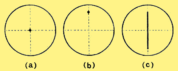
Fig. 2. - Appearance of the screen of the tube of Fig. 1. (a) When no voltage is applied to the deflector plates. (b) When a steady voltage is applied to the deflector plates. (c) When an alternating voltage is applied to the deflector plates.
The appearance of the screen resulting from the application to the deflector-plates of zero voltage, a steady voltage, and an alternating voltage can be seen from Fig. 2.
The Time Base
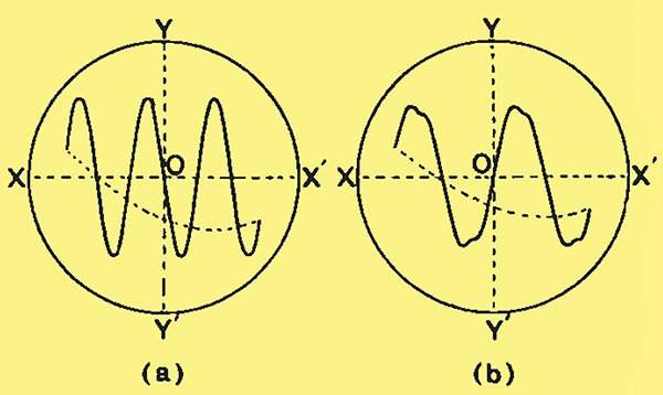
Fig. 3. - (a) The trace of an oscillograph screen produced by combining an alternating voltage (vertical scale) with a linear horizontal traverse (time-base). (b) The same, for an alternating voltage of bad wave form.
If a cathode-ray tube is to be of any real service in studying an alternating voltage the line of Fig. 2c must be developed into some more informative figure. This line is produced by the rhythmic up-and-down movement of the spot of light, which follows faithfully at every instant the voltage applied to the deflector plates. Let us suppose that the spot of light is given a horizontal movement independent of the vertical movement we are trying to study. and let us further suppose that this horizontal movement consists of a single trip across the screen at constant velocity from left to right. The up-and-down movement still continues, but the added left-to-right movement means that as the spot moves upwards the path it traces out is no longer vertical, but is slanted over to the right, the slant increasing as the spot slows towards the end of its travel. At the moment when the upward movement has ceased and the downward movement is about to begin the travel is purely horizontal, while as it comes downwards the path is again deflected towards the right. The whole pattern traced out will be seen by an observer in a form something like that shown in Fig. 3a.
If the left-to-right movement takes place at constant velocity every inch along the horizontal axis XOX1 represents some definite period of time. Similarly, every inch along the vertical axis YOY1 represents some definite voltages applied to the deflector-plates; the curve traced out, therefore, is a graph of this voltage plotted against time. It is the waveform of the alternating voltage we have been trying to study. In Fig. 3a a more or less conventional sine-wave is shown, but we may find that the voltage in which we are interested contains components of several different frequencies, in which case some 'distorted' wave, such as the remarkably bad specimen exhibited in Fig. 3b, may make its appearance on the screen. The distortion may be then traced to its source and eliminated, if such is the purpose for which the alternating voltage is being examined.
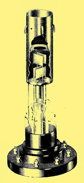
Fig. 4. - Internal construction of Cossor cathode-ray oscillograph. Bulb and fluorescent screen not shown.
The second sweep of the electron-beam. that from left to right, requires a second pair of deflector-plates set at right-angles to the single pair indicated in Fig. 1. The photograph of Fig. 4 shows the electrode assembly of an actual cathode-ray tube, and shows very clearly the two pairs of deflector-plates one above the other. Immediately below them is the anode, the central hole in which is clearly visible. Round the filament is a cylindrical electrode, usually known as the shield, to which in practice a negative potential is applied. The effect of this, combined with a small amount of an inert gas within the tube, is to assist in focusing the electron beam so as to give a small spot rather than an ill-defined bright patch on the screen, and hence to provide figures traced out by a thin, clear line. A further effect of the shield is to increase the number of electrons passing through the anode hole.
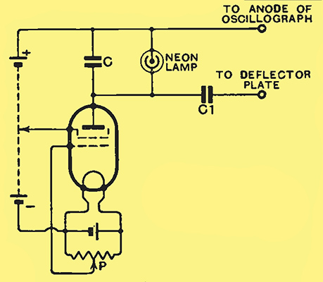
Fig. 5. - A simple linear timebase circuit.
For providing the voltage applied to the second pair of deflector-plates to give the left-to-right sweep of the beam a time-base circuit is required. In one of its simplest forms this may consist of a capacitor C shunted by a neon lamp (Fig. 5), together with means for charging the capacitor from a steady current source. When the voltage across C, receiving a charge from the battery, rises to the striking voltage of the neon lamp the latter lights, thereby drawing a current which discharges C to the voltage at which the lamp will no longer stay alight. Recharge to the striking voltage then begins again, and so the process continues, the voltage on C showing in continuous succession a slow rise followed by a sudden drop. The slow rise is used to carry the spot from left to right across the screen, while the sudden drop sends it back at high velocity to begin its traverse over again.
The current through the screen-grid valve used as constant-current device may be controlled by adjustment of the grid-bias potentiometer P; this, in conjunction with the choice of screen voltage, allows the rate at which occurs the charge and discharge of the capacitor to be controlled. By making this process take, say, three times the period of a single cycle of the alternating voltage under examination, three complete waves of this voltage appear on the screen. But it will be appreciated that it will only be when the three-to-one ratio is absolutely exact that successive repetitions of the picture will occupy exactly the same place on the screen ; a slight variation from the intended ratio will cause the waves seen to progress steadily across the screen as each successive figure makes its appearance a shade to right or left of the last.
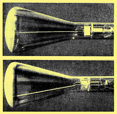
Two actual photo-graphs showing the projected beam of electrons. The beam in its normal position is shown at the top, whilst the effect of deflecting the beam is represented below.
|