|
A Receiver which can be Confidently Regarded as Embodying the Most Advanced Practice in Modern Superheterodyne Design. Inaudible Background and Ultra-selectivity Incorporating Stenode Principles.
- Features of the set -
- Single-dial seven-valve AC superheterodyne with variable-mu HF and IF stages.
- Screen-grid 1st detector, and triodes for the oscillator, 2nd detector, tone corrector and output stage.
- Special band-pass filters with a total of eight tuned circuits and one stage of tone correction allow of high-note reproduction up to 5 kHz with extremely high selectivity.
- Volume control acting simultaneously on the grid bias of both variable-mu valves with additional local distance switch. Free field current for moving coil speaker. Undistorted power output 2,5 Watts.
- Special oscillator tracking arrangements to simplify ganging of the oscillator and pre-selector circuits and to secure freedom from second channel interference.
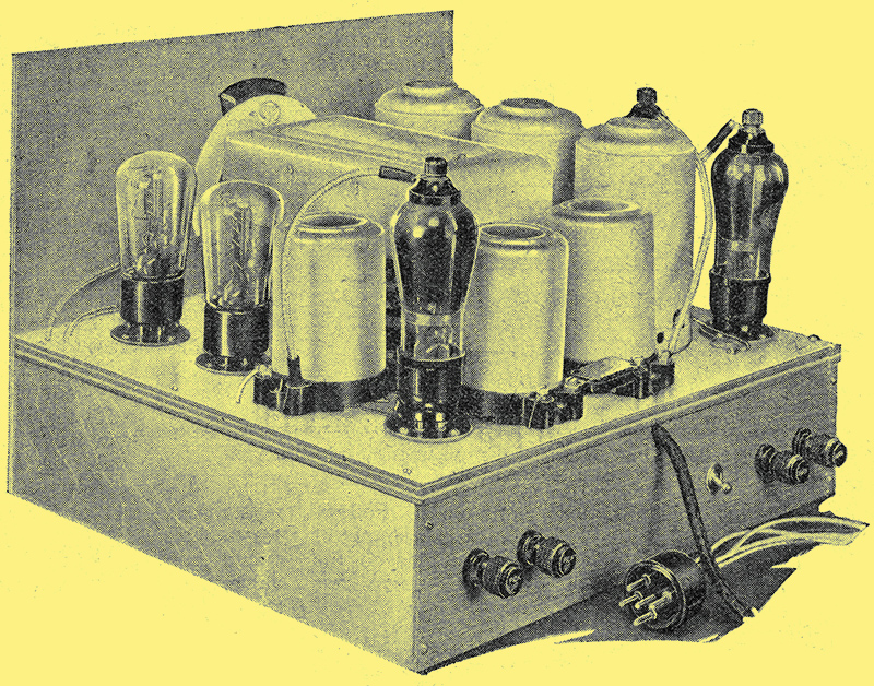
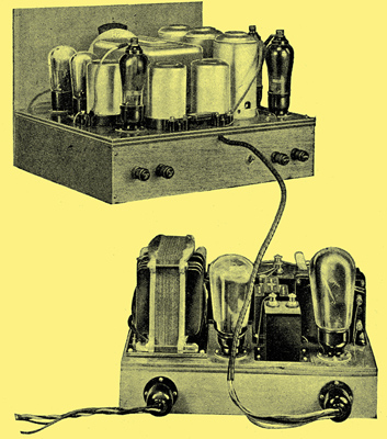
Top view of completed chassis.
There can be little doubt that faithful reproduction is the primary requisite of a broadcast receiver. High quality alone, however, is insufficient for the complete enjoyment of broadcasting, for this can only be attained when the reproduction contains everything transmitted by the desired station and nothing from any other source. The ideal receiver, therefore, must be capable of reproducing the whole range of audible frequencies without distortion, and it must be sufficiently selective to eliminate interference from all sources, while the set itself must not introduce noises.
In the past, these exacting requirements have been incapable of fulfilment, except in the case of a purely local station receiver with which neither interference nor set noises are usually of any importance. Recent developments in radio, however, have resulted in the possibility of building a set which, so far as the more powerful of distant stations are concerned, may truthfully be said to approach very closely to the ideal. The complete attainment of all the attributes of the ideal receiver is, of course, still impossible.
A theoretical account of the latest circuit developments was given here, and it may be said that a set built in accordance with the principles there outlined will give a very satisfying performance. Full reproduction of all audible frequencies up to a limit of about 5 kHz is possible, While retaining a degree of selectivity sufficient to eliminate interference when receiving the stronger of distant stations. The high quality and freedom from modulation interference are retained on the weakest stations, but the possibility of sideband heterodyning from adjacent stronger stations has not yet been overcome. Except when the receiver is being worked at a point approaching its maximum sensitivity, at which point even the weakest stations are normally receivable at good strength with any reasonably efficient aerial, noises introduced by the set itself are so low as to be inaudible.

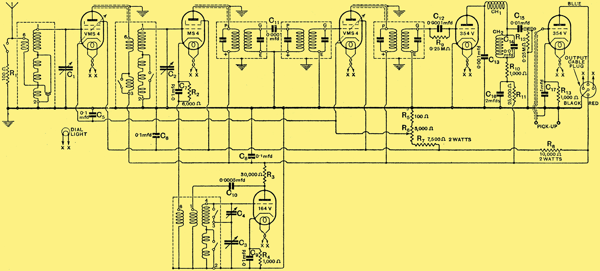
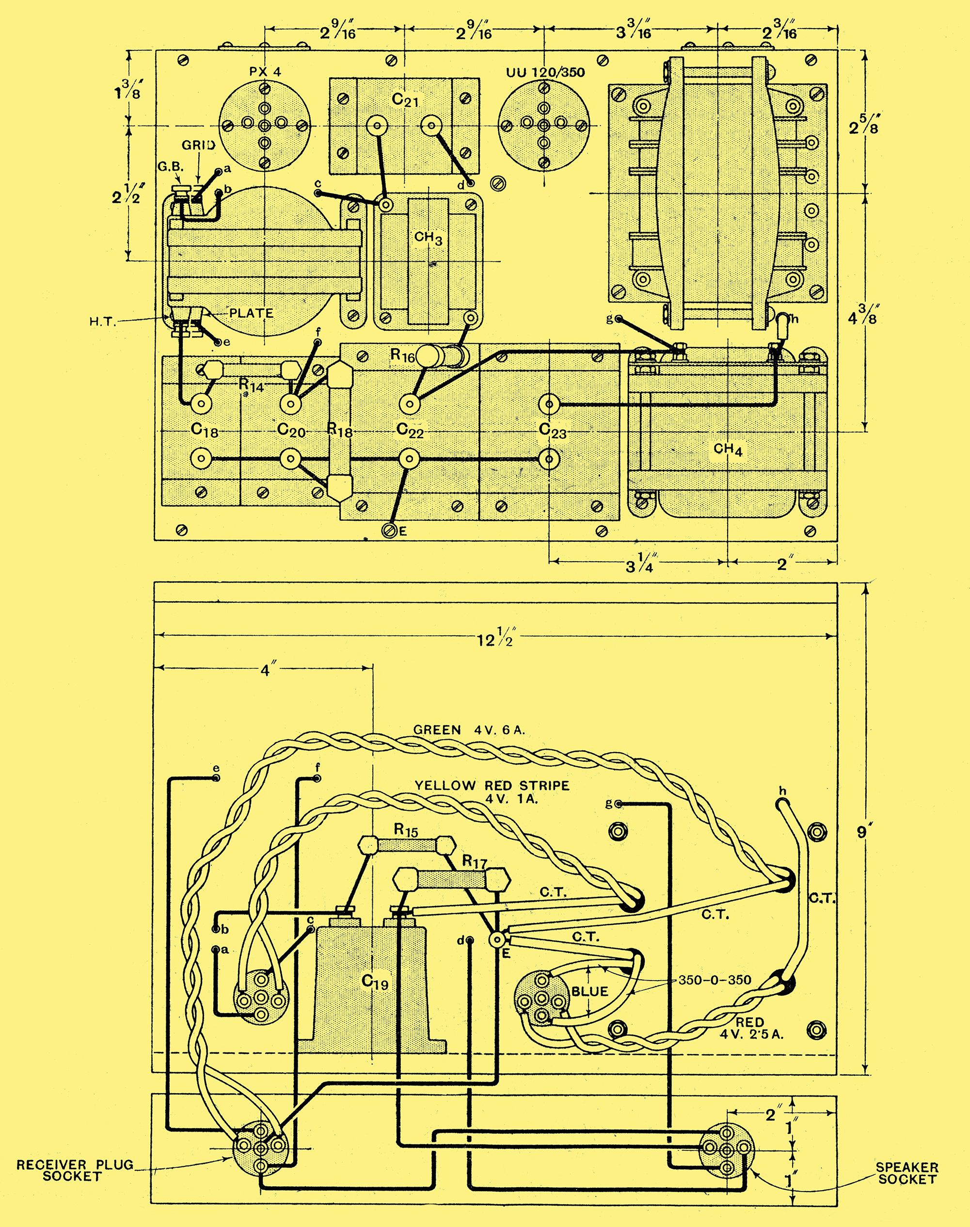
Fig. 1. - The receiver portion of the Monodial AC Super. The leads XX are each run in duplicate in the connecting cable to reduce the resistance; one pair are coloured yellow and white and the other brown and green.
In view of the fact that the circuit principles have already been fully described, in the present article we shall proceed to the actual constructional details of a practical receiver, and consider only those precise details which, although not affecting the general principles, are by no means unimportant, and upon which the success or failure of a receiver so largely depends. The circuit diagram of what may be termed the receiver portion of the apparatus is shown in Fig. 1 and that of the power unit, which includes the mains equipment and the output stage, in Fig. 2, and it will be seen that the former unit contains six valves which are employed in an HF stage, first detector, oscillator, IF stage, second detector, and tone corrector stage.
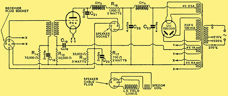
Fig. 2 - The power unit, including the output stage, which is built as a separate unit.
The Pre-Selector
In order to keep second channel interference at a minimum, two tuned circuits are used to precede the first detector, and as an HF stage is employed, one takes the form of the aerial tuning circuit, while the other provides the inter-valve coupling. The total selectivity of the signal frequency circuits, therefore, is rather greater than with the more customary band-pass filter, while their characteristics are such that a negligible amount of sideband cutting is introduced.
For maximum efficiency the so-called aperiodic aerial coupled is used, and the switching is so arranged that on both wavebands the aerial load is substantially constant, thus avoiding ganging errors. The circuit, whose inductance is matched to that of the inter-valve coupling, is tuned by one section C1 of the special 0.0005 μF. three gang capacitor. In order to avoid cross-modulation and to provide a distortion-less pre-detector volume control, the HF valve is of the VMS4 variable-mu type, and is coupled to the first detector by means of an HF transformer. A transformer coupling is used in preference to other methods, partly because of its simplicity, and partly because a high resistance in the first detector grid circuit can be readily avoided. This circuit is tuned by the second section C2 of the gang capacitor, a section which is in every respect identical with C1.
The MS4 first detector is employed as an anode bend rectifier, and is self-biased in the usual way by a 6,000 Ω resistance R2, shunted by a 0.1 μF capacitor C7, in its cathode lead. A valve with a comparatively low mutual conductance has been deliberately chosen for use at this point, since it has been found to introduce less background noise than more efficient types, and it has also a greater signal input handling capacity.
The oscillator is a separate 164V valve with its grid circuit tuned. It is biased by the 1 kΩ resistance R4, shunted by the 0.1 μF capacitor C9, in its cathode lead, and its HT supply taken from the common 200 Volts line through the 30 kΩ resistance R3. The reaction coil is shunt fed from the anode circuit through the 0.0005 μF capacitor C10, and the coupling between the first detector and oscillator circuits is provided by means of a coupling coil connected in series with the first detector cathode lead.
The medium waveband tuned oscillator winding has an inductance considerably less than that of the two pre-selector circuits, and it is tuned by the third section C3 of the three-gang capacitor. This section of the capacitor has plates specially shaped so that the correct frequency displacement of 110 kHz between the oscillator and pre-selector circuits is accurately maintained over the whole of the medium waveband, without the necessity for using special tracking capacitors. This correct ganging, however, is not maintained automatically on the long waveband, and it is necessary to introduce a series padding capacitor C4, which is adjustable over a capacity range in the neighbourhood of 0.001 μF, and which is short-circuited on the medium waveband by a switch built into the coil base. Ganging adjustments are thus reduced to a minimum, and it is readily possible to obtain the accurate alignment of circuits which is so essential for the avoidance of second channel interference.
The primary circuit of a four stage filter tuned to the intermediate frequency of 110 kHz is included in the anode circuit of the first detector. This filter consists of two pairs of mutually coupled coils, themselves coupled together by the 0.0001μF capacitor C11 between the high potential ends of the coils. Following this filter is the IF stage, which consists simply of a single VMS4 variable-mu valve coupled to the second detector by means of the usual type of two-stage filter.
The Voltage Supply Circuits
Since the valves do not all operate upon the same signal frequency, it has been found possible largely to dispense with de-coupling without any fear of introducing unwanted feed-back effects. The anode voltages of the two variable-mu valves and the first detector are all taken directly from the common 200 Volts line, with a single 0.1 μF capacitor C8 shunted to earth. The screen grids are similarly fed from the same tapping on a voltage divider shunted across the HT supply, and with another 0.1 μF capacitor C6 shunted to earth. This voltage divider is made up of R8 and R7, which have values of 10 kΩ and 7,5 kΩ respectively, and are of the 2 Watt type, in series with the 5 kΩ volume control potentiometer R6, and the 100 Ω resistance R5. The cathodes of the two variable-mu valves are joined together and taken to the slider of the volume control, while a 0.1 μF capacitor C5 is shunted to earth.
The bias impressed on both the variable--mu valves, therefore, is the same, and varies from a maximum of some 60 Volts to a minimum, provided by the voltage drop along R5, of 2.5 Volts. A complete control of volume is thus obtained by means of a single potentiometer, for the amplification of both the HF and the IF stages is controlled simultaneously. It has been found, however, that distortion may sometimes occur when receiving a strong local station at low volume, and for local reception some means of reducing the aerial input is often desirable. A 'Local-Distance' switch is fitted, therefore, whereby a resistance R1 of 100 Ω may be connected at will between the aerial and earth terminals.
Tone, Correction
A 354V type valve is used as a power grid second detector, and the grid leak and capacitor, R9 and C12, are given the usual values of 0.25 MΩ and 0.0001 μF respectively. The usual IF filter is fitted to the anode circuit, and consists of a high-inductance choke Ch1 and a 0.001 μF capacitor C13, but the inter-valve coupling is of an unusual type, since its purpose is to provide a degree of tone it correction for the sideband cutting of the tuned circuits. In place of the usual resistance, therefore, a network of capacity, inductance, and resistance is employed.
This network consists of the parallel resonant circuit, Ch2 and C14, in series with the 1 kΩ resistance R10. At low frequencies the coupling is provided only by the circuit resistance, which consists of R10 in series with the choke resistance of 250 Ω, giving an effective value of 1,250 Ω. For quite high audible frequencies, the circuit impedance does not greatly depart from this value, and so the stage amplification remains fairly constant at a low value. When a certain frequency is passed, however, the impedance, and hence the amplification, rises rapidly until the resonance frequency of some 5 kHz is reached, and the amplification is nearly equal to the amplification factor of the valve.
The choke Ch2 has a value of 90,000 μH and it is important that in this case the specified component be employed, for the compensation obtained is dependent not only upon the inductance, but also upon the choke resistance. The shunt capacitor C14, has a capacity of 0.01 μF, and so gives a resonance frequency of about 5 kHz. The inter-valve coupling is completed by the usual 0.01 μF. grid capacitor C15, and a 0.25 MΩ. grid leak R12, while the detector anode circuit is fed from the 200 Volts line through the 25 kΩ de-coupling resistance R11, with a 2 μF capacitor C16 shunted to earth. The radio-gramophone switch is connected to give a single-pole change-over action, and is joined directly in the grid circuit of the 354V tone corrector or first LF valve, which is biased by a 1 kΩ resistance R13, shunted by a 1 μF capacitor C17 in its cathode lead.
The coupling between this valve and the PX4 output stage is by means of a 3.5:1 ratio transformer, which is fitted in the power unit, and the tone-corrector anode circuit is de-coupled by the 10 kΩ resistance R14 and the 2 μF capacitor C18. The output valve, which delivers some 2,5 Watts to the speaker, is biased by the 700 Ω (2 Watts) resistance R17. connected between negative HT and the centre tap of its filament-heating winding on the mains transformer, and its grid circuit is de-coupled by a 50 kΩ resistance R15 and a 1 μF capacitor C19. A choke-feed output circuit is employed with a 20 H choke Ch3 in series with a 1 kΩ 2 Watts resistance R16, whose purpose it is to prevent excessive anode voltage being applied to the output valve. The loud speaker or output-transformer primary is, of course, fed through the 2 μF capacitor C21 in the conventional manner.

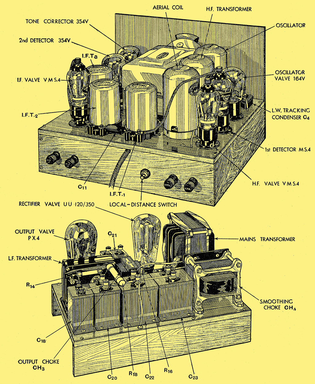
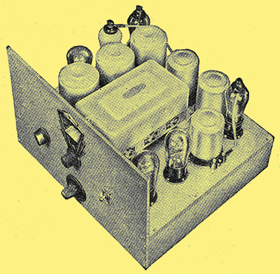
The receiver and eliminator units. The output stage is included in the mains chassis so as to localise all high-voltage equipment.
The Power Unit
A UU120/350 valve rectifier is used, and delivers some 360 Volts at 100 mA across the 4 μF capacitor C23. The whole current is smoothed by the 10 H choke Ch4, in conjunction with another 4 μF capacitor C22, and the supply for the output valve is then tapped off. The remainder of the current, some 50 mA, flows through the 2,500 Ω field winding of the moving-coil loud speaker, where it is still further smoothed in conjunction with the 2 μF capacitor C20. In order to provide sufficient current for adequate field excitation under all conditions, a 25 kΩ 3 Watts resistance R18, is connected across this capacitor, where it also tends to stabilise the anode voltage of the early valves.
The mains transformer carries secondaries giving voltages of 350-0-350 Volts at 100 mA for HT, 4 Volts at 2.5 Amps for the rectifier filament, 4 Volts at 1 Amp for the output-valve filament, and 4 Volts at 6 Amps for the six early valves and the light illuminating the dial.
Now it is well known that modulation hum is usually due to the presence of HF currents in the mains being transferred to the receiver circuits through the capacity between primary and secondary windings. It is the usual practice to eliminate this undesirable effect by connecting capacitors between the mains and earth, so that the HF currents are by-passed to earth and do not enter the circuits of the receiver proper. While this scheme is very effective, it has been found that in cases where the earth lead is very long, there is a tendency for background noise to be increased. Since every possible precaution against background noise has been taken in this receiver, an alternative method of eliminating modulation hum has been thought advisable. The primary of the mains transformer is electrostatically screened from the secondaries by means of earthed copper strips interposed between the windings, and it has been found that this method is as effective as the older scheme.
Construction
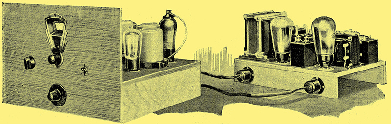
Why the building of the Monodial AC Super described theoretically last week is unusually easy is partly explained by the use of two separate units - the receiver and its power chassis.
Continuing the description of the Monodial AC Super, it will be observed that there are two separate units the receiver and power chassis. For this there are several reasons, of which the most important is that the constructional work is simplified owing to the reduction in size and weight of each individual unit. Where the superheterodyne is to be fitted to a cabinet of the radio-gramophone type, moreover the two-unit construction lends itself to an economy of space, since the receiver can be placed on one shelf, with the power unit and loud speaker on the other. A further point is that the mains equipment and output stage are available for use with other receivers if desired, and any modifications to the output stage which might be necessary for abnormally large volume are more readily carried out.
The first six valves are all mounted on the receiver chassis, which is built of aluminium-covered ply-wood mounted on battens. This special wood is known as Venesta, and may be obtained with the large holes already cut. If un-drilled material is obtained, however, these large holes, which have a diameter of one inch and are for the valve holders, can be readily cut with an ordinary brace and bit, since the aluminium covering is only thin. The first step in the construction is to mount the base on the battens, and then the valve holders, taking care that none of the valve legs come into contact with the metal covering of the wood. The components above the baseboard should next be mounted with the exception of the gang capacitor, and it may be remarked, in passing, that the aluminium covering to the base is easily pierced with a pricker.
The under base components are then screwed in position, and the wiring begun. With the exception of the three leads which run to the gang capacitor, all the coil connections should be made first. No. 22 gauge tinned copper wire is used and run in small-diameter sleeving, and in most cases the leads are taken directly from point to point by the shortest path. Few soldered joints are necessary, and the metallised resistances are supported entirely, by their connecting leads to other components; care should be taken, however, to see that the leads to these resistances do not come into contact with the metal cases of fixed capacitors.
A separate pair of twisted leads must be run to each valve holder and the dial light for the heater wiring in order to avoid an excessive voltage drop at one end the seven leads are twisted together and inserted into the junction block for connection to the inter-unit cable. Screened leads are used for the anode connections to the three screened-grid valves, and for two of the connections to the radio-gramophone switch. The type of screening recommended is that in which a piece of large diameter sleeving is provided with a braided metal covering. The material should be cut to the correct length, and the metal covering pushed back at each end so that about one-eighth of an inch of the sleeving projects. A few turns of tinned copper wire should then be wrapped round each end and soldered in position to prevent any possibility of the covering coming into contact with the internal wire. The screening should, of course, be earthed by joining one end to a convenient earth point on the chassis.
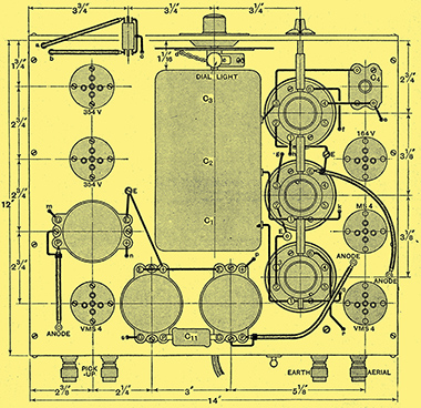 
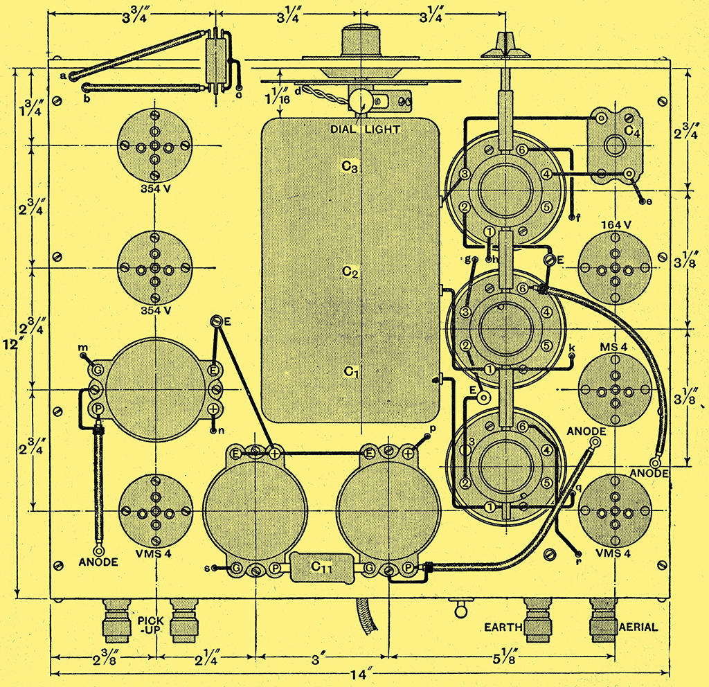
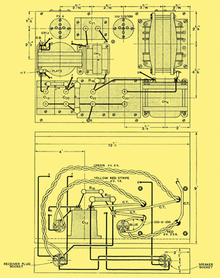
Dimensional data of the components above and beneath the baseboard. Practically all the wiring is carried out on the underside.
Having completed the wiring, three leads should be attached to the three terminals of the gang capacitor, and this component secured to the chassis. The contact of the capacitor with the metal covered baseboard provides a sufficient earth connection, but care should be taken to see that the holding-down screws are well tightened up. The three connections to the coils can now be completed, and the dial and front panel placed in position.
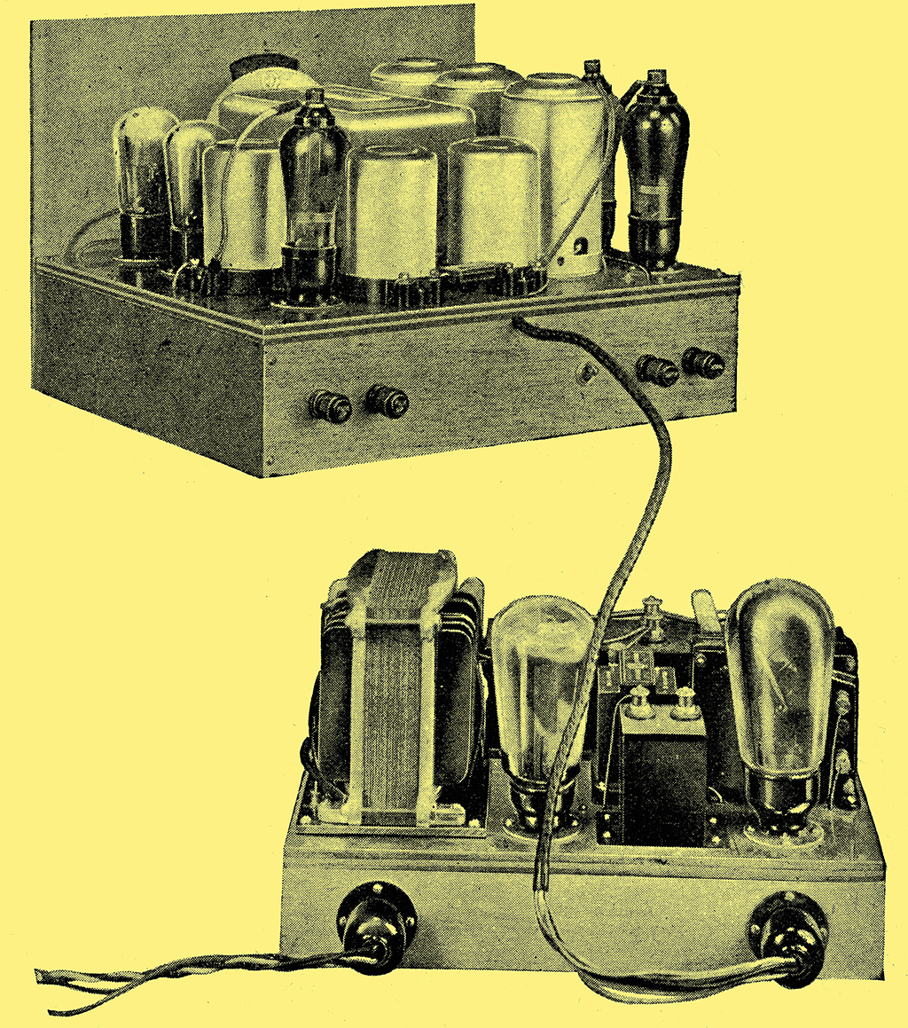
The Inter-unit Cable
The receiver and power unit connected by cable. A four member connector is used for the field and speech coil leads.
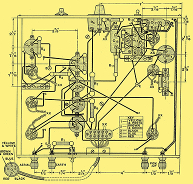
The receiver should now be complete with the exception of the inter-unit cable, which is terminated at one end by a five-pin plug and at the other by the junction block. The pins on the plug are arranged in the same way as on a valve base, and, in fact, it fits into an ordinary valve holder; it is convenient, therefore, to refer to them individually by the familiar valve-pin names. In connecting up the cable great care should be taken to avoid errors and short-circuits, and it will be a help in this respect if the colour code shown on the drawing is adhered to. The black and red wires should be used for joining the negative and positive HT lines to the cathode and anode pins respectively of the plug, while the blue wire must connect between the anode of the tone-corrector valve and the grid pin.
Since a seven-wire cable is used, and there are only five connections, four wires will remain. Of these, the white and the yellow wires are connected together at each end, and the two wires are then treated as a single lead and used for the connection between one side of the receiver heater wiring and one heater pin in the plug. Similarly, the green and brown wires are joined together at each end, and provide the other lead between the heater wiring and the other heater pin. Two wires in parallel are used for the heater connections in order to avoid an excessive voltage drop along the cable, and for the same reason it is important to note that a longer cable than that specified should not be employed.
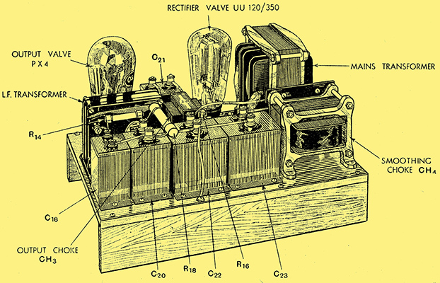
The Power Supply and Audio Output Stage Assembly.
The power unit is built upon a chassis of aluminium-covered ply-wood, and carries two valve holders for the output and rectifier valves. Two further valve holders are mounted on the rear supporting batten for the receiver and loud speaker plugs; and this vertical mounting is adopted in order to prevent confusion with the valve holders proper. Since the LF transformer is fitted with reversible feet, it can be mounted on its side in the correct position without difficulty, but care should be taken to see that both this component and the mains transformer are fixed in exactly the relative positions shown in the drawings, or trouble from hum may be found.
The power unit from above and below. It is important that the relative dispositions of the LF and mains transformers should be maintained.
In cases where either the mains transformer or the LF transformer is of e different type from those specified, the LF transformer should not at first be screwed down, and it should be connected up with long, flexible leads. When the set is first tried out it can then be readily moved into the position of minimum hum, and once this is found it can be screwed down and permanently wired up. It should be emphasised that this procedure will be unnecessary if the specified components be employed.
The mains transformer is fitted with coloured leading out wires instead of terminals for the various secondaries, and care should be taken to connect these up correctly in accordance with the colour code supplied with the transformer. The leads are of amply sufficient length to reach to the various connecting points without difficulty. The mains terminals are mounted on a strip carried by the transformer itself, and the mains connections are, therefore, taken directly from them.
Only four of the sockets of the valve holder used for the speaker connections are employed, and in the plug which fits this socket the field winding of the speaker is wired, to the grid and anode pins, and the speech coil, or the primary of the output transformer if this be used, to the two filament pins. In cases where the speaker does not require field current from the set the plug connections should still be retained, but the wiring to the grid and anode sockets omitted. Additional smoothing will be necessary, and a 20 H choke of a type similar to that used for the output choke, fixed to the base in the space left for it, and a 2 kΩ 10 Watts resistance wired in series with it. This combination should then be treated as if it were the speaker field shown in the circuit and wired between capacitors C20 and C22.
The output stage and eliminator are built together as a separate unit.
If it be desired at times to use an energised type of moving-coil speaker and at others to use a non-energised type, then the power-unit connections should all be made exactly to specification. The energised speaker should be connected in the normal way to its plug connector, but the non-energised speaker should be wired to the filament pins of another plug, to the grid and anode pins of which are connected the series combination of a 20 H choke and a 2 kΩ 10 Watts resistance. In this way the alterations required to the smoothing system for the different types of speakers will automatically be made on inserting the plugs.
Throughout the apparatus all nuts should be well tightened up so that secure connections are made but care should be taken, in the case of the valve holders, not to apply too much force, or wires may be cut through. The coil and capacitor covers should fit tightly, and screened leads should not be allowed to rub against metalwork, for, even if both be earthed, an intermittent contact may cause noisy reception.
The wiring should be carefully checked over before putting the set into operation, and it is a wise plan to check the continuity of the various circuits with the aid of a voltmeter and battery, for it is easy to overlook one of the many earth connections. It is a safe plan, also, to test the various components before building the set, as it eliminates one possibility of trouble. Coils should be tested for continuity, and capacitors to make sure that there is no internal short-circuit.
If desired, a switch of the quick-make-and-break type can be joined in series with one of the mains leads, and mounted on the power unit. The position of such a switch is in no way critical, but on no account should the mains leads be allowed to wander near the output valve or the LF transformer. When the receiver is first switched on hum will be found, and will persist for, say, thirty seconds, after which it will gradually die away as the early valves warm up.
The set will not function for half a minute or so after the hum has disappeared, for the oscillator valve takes the longest to warm up, and until it is working nothing at all will be receivable. Apart from its circuit constants, the exact, frequency generated by the oscillator depends to some extent upon its anode voltage and heater temperature. As completely stable conditions are not reached for some time after the set is switched on, the oscillator frequency may wander slightly during the first quarter of an hour or so. Any station which is tuned in during this time, therefore, may require slight retuning when conditions have become completely stable, but thereafter stability should be maintained indefinitely.
Although results should be obtainable as soon as the construction has been completed, correct functioning cannot, of course, be expected until the various preliminary adjustments have been carried out. These adjustments are a matter of the first importance, for, if the receiver be correctly built, its success depends entirely upon the accuracy with which they are carried out.
Tuning Up The Monodial
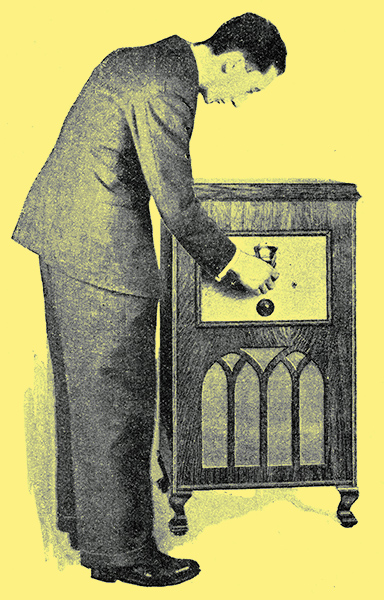
The Monodial in Action.
Obtaining a Balance Between Selectivity and Quality.
The salient features and construction of the Monodial AC Super have been fully dealt with, and it now remains to describe those initial adjustments which are so essential for the correct operation of the receiver. As completely stable conditions are not reached for a short time after the set is switched on, some quarter of an hour should be allowed to elapse before starting the adjustments, and this interval may well be occupied by making a rough check on the operating voltages and currents. These should be measured with the volume control at maximum, with the wave-range switch set for the medium waveband, and with the aerial disconnected so that no signal is audible.
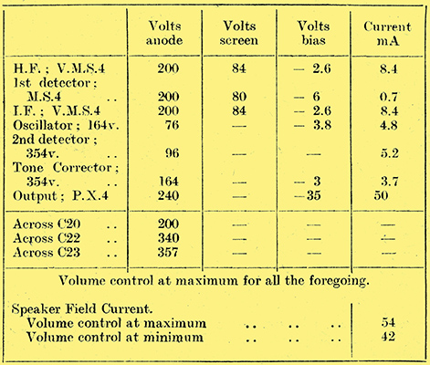
Table of Voltages.
The values obtained should agree fairly closely with the figures given in the table, but complete agreement cannot be expected, since individual valves and components vary somewhat, and the mains themselves may not have their rated voltage at the time of testing. Provided, therefore, that the various voltages and currents are of the same order as those obtained with the original receiver, it may safely be assumed that the mains equipment, feed-circuits, and valves are functioning and the initial adjustments can be proceeded with.
These initial adjustments fall into three categories, anal must be carried out in the order named: first, the tuning of the lF circuits; secondly, the ganging; anal, lastly, the balancing of the selectivity and quality. The two earlier processes are carried out by tuning for the maximum signal strength, and, if care be taken, the ear is a sufficiently accurate indicator. If a milliammeter be available, however, the adjustments, are made much easier by connecting it in the second detector anode circuit, and using the change of anode current with signal as at precise indicator of signal strength. A convenient point at which to connect a meter, which should have a full-scale reading of about 10 milliamperes, is in series with R11 shown in Fig. 1.
The IF Tuning
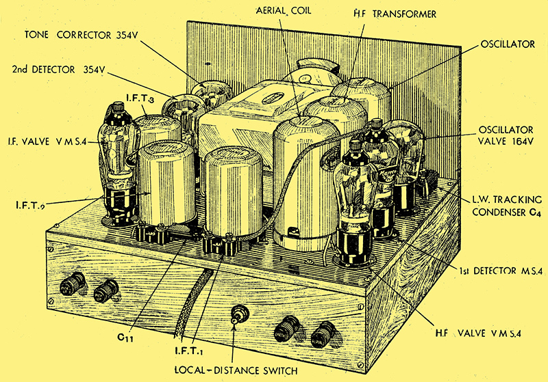
The receiver unit with principal components identified.
The coils in all three IF transformers should be set at nearly their maximum distance apart, and a station tuned in as accurately as possible. The strength of this station should be adjusted to a conveniently low level, at which changes of strength are readily detectable, by means of the volume control. Each of the six levers projecting from the bases of the IF transformers must then be adjusted in turn for the maximum response, and when this has been done its should be found that a movement of any lever in either direction results in a reduction of signal strength. If it be found that maximum strength occurs with any lever pushed over to the full extent of tits travel, then all the other levers should be moved slightly in the opposite direction and the station retuned by the gang capacitor. This changes the intermediate frequency slightly, and a readjustment of all the levers should now allow of the correct conditions being obtained.
During this process it will probably be found necessary to lower the setting of the volume control as the circuits come into tune, so that the increased signal strength does not lead to overloading of the second detector. This point should be carefully watched, for it is hopeless to attempt to adjust the circuits on a signal so strong that the valves are overloaded.
When the IF tuning has been completed it should be found that, although the input circuits are not correctly ganged, a number of stations are receivable, and the setting of the tuning dial should be critical. A station on a low wavelength should be chosen so that the ganging adjustments can be carried out. This station should preferably tune-in within the first ten degrees on the dial, and it should not be one greatly subject to fading. If it be found, however, that the circuits are so badly out of tune that no very low wavelength station can be heard, a somewhat higher-wavelength station, such as the London National, should be used to get the circuits approximately in tune.
Before tuning-in this low-wave station, the trimmer on the oscillator section of the gang capacitor should have been slacked off by one or two turns, and the other two trimmers nearly fully unscrewed.
The Ganging
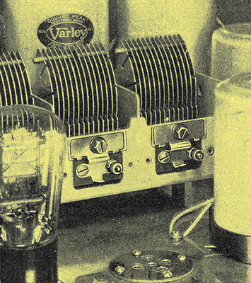
The layout is so arranged that there is easy access to the trimmers on the ganged capacitor members. The oscillator trimmer is behind the valve in the foreground.
The station is tuned-in as accurately as possible by the main tuning control, and the two trimmers on the first two sections of the gang capacitor each adjusted for maximum response. The trimmer on the oscillator section should not be touched unless it be found that either of the other trimmers has reached the full extent of its capacity range. If, for instance, it be found that one of the preselector trimmers is fully unscrewed, then the oscillator trimmer should be screwed up slightly and the station retuned at a slightly lower setting of the main dial. By proceeding on these lines it will readily be possible to arrive at settings such that any further alteration to the preselector trimmers gives a reduction in signal strength.
The circuits are now accurately ganged at the high-frequency end of the tuning range, and it should be found that stations can be tuned-in over the whole of the Medium Waveband. Unless the stray circuit capacities have their correct relative values however, the ganging may be slightly out at high dial readings, and so the next step is to correct for this. A station working with a frequency of about 550 to 600 kHZ (550 to 500 metres) should be tuned-in, and the trimmer on the oscillator section of the gang capacitor adjusted while rocking the tuning dial backwards and forwards over a few degrees until the optimum combination of settings is found. On no account should the preselector trimmers be adjusted at this wavelength.
When this adjustment is completed, a return should be made to the high-frequency (low-wavelength) station, and the preselector trimmers readjusted. This completes the medium waveband gauging, and the next step is to perform the same operation on the long waveband. This is considerably easier, since there is only one adjustment, and it is far less critical. Either Huizen or Radio-Paris should be tuned-in with the padding capacitor C4 set at about one-half its capacity. If any difficulty be experienced in finding one of these stations, the tuning dial should be set for it in accordance with the list of dial settings given herewith, and the adjustment carried out by means of C4 alone. When the station has been found, C4 is adjusted while rocking the tuning dial backwards and forwards until the optimum combination of settings has been found.

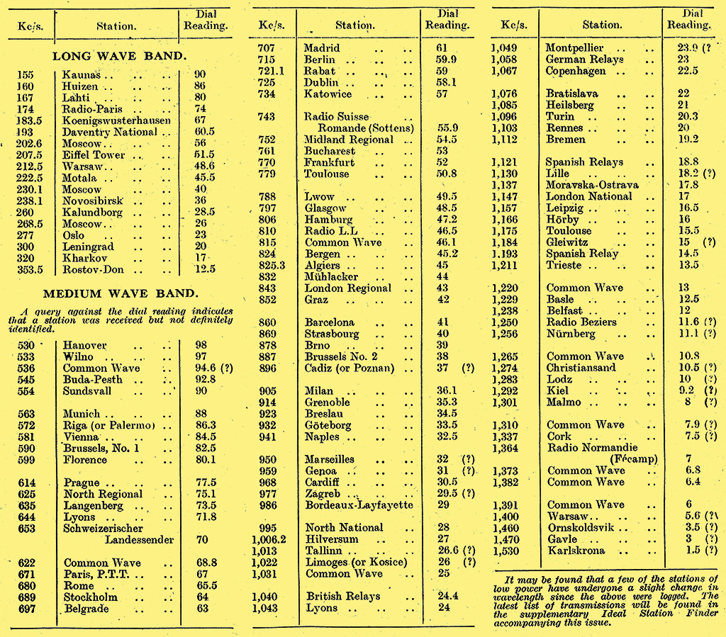
Tuning dial readings for 120 stations.
This completes the ganging, and it should be found that stations are receivable, and tune-in very sharply, at all points over the dial, but both the sensitivity and the quality of reproduction will be below normal. Before proceeding to discuss the quality adjustments, however, it is as well to repeat that, while carrying out the ganging on the medium waveband, the preselector trimmers must be adjusted only at a low wavelength, and never at a high, and the oscillator trimmer only at a high, and while rocking the gang capacitor. On no account must any of the three trimmers on the gang capacitor be adjusted on the long waveband, otherwise the medium wave ganging will be seriously wrong.
The final points to receive attention are the coil positions of the IF transformers, and these should he adjusted for the best quality of reproduction. In general, the coils in the first transformer should be set with 29/32 in between the adjacent faces of the formers, and the coils in the third transformer with ¼ in between adjacent faces. The second transformer coupling can then be regulated to suit the characteristics of the particular loud speaker which is being used. With the particular speaker used during testing this distance was found to be ½ in. When carrying out this adjustment care should be taken to select a station which is known to be transmitting with good quality, for certain foreign stations are sometimes defective in this respect.
A general test should now show that the sensitivity has increased considerably, and it should be possible to tune-in stations over the whole of the dial, with each transmission quite separate and distinct from its neighbours in cases where their separation is not less than 9 kHz. An efficient aerial and earth should be used in most cases, but where the set is to be worked at a very short distance from a powerful local station it may be found that better results are had with a small aerial.
On test, the 120 stations given in the accompanying list were logged in a single evening, and while the Brookmans Park stations were working, the receiver being located some nine miles away. Prague and Breslau both suffered somewhat from second-channel interference due to the two London transmitters, which were also responsible for a considerable amount of interference on Graz, Leipzig, and Moravska-Ostrava. Muhlacker, which is spaced 11 kHz from the London Regional and is a stronger signal, could normally be received without serious interference. Any interference, of course, took the form of sideband heterodyning, and was at its worst during deep modulation of the London transmitter, being particularly bad during the reading of the News Bulletin.
On the remainder of the more powerful Continental stations no interference was experienced other than occasional chirps due to sideband heterodyning. Except where the transmission itself was distorted the quality on all stations was equally good, and reached a standard which would satisfy the most critical. The sensitivity proved ample for the reception of the weakest stations, and at no time had the volume control to be set at maximum, even although the aerial was of only a moderately efficient type.
Of the 120 stations which can be received, some forty to fifty are at times available sufficiently free from interference for their programmes to be of entertainment value, and on any given night a choice of about twenty stations is obtainable. During the summer months, of course, atmospheric conditions make reception poorer, but a reasonable number of alternatives to the local should be available. Even when conditions are poor the receiver is sufficiently sensitive to bring in distant stations, and it is the background produced by atmospherics, rather than lack of amplification, which is likely to prove the limiting factor. Background noises introduced by the set itself are at a minimum, and, in the case of the stronger stations, are inaudible.
Before concluding, some general remarks on the receiver may be of interest. The quality of reproduction is very largely dependent upon the loud speaker employed, and as good a type as possible should be used. If advantage be taken of the provision for free field current, the speaker should be a model requiring some four to six Watts for field excitation, since these figures represent the maximum and minimum powers obtainable at the maximum and minimum settings of the volume control. Unless it is already of the correct impedance, the speaker should be fitted with a transformer of such ratio that its average primary impedance is 4 kΩ, but the output choke must be retained whether a transformer is used or not.
In perhaps the majority of cases the local-distance switch will prove an unnecessary refinement. Where the set is used close to a local station it may prove advantageous in avoiding distortion with that station. Furthermore, under such conditions it may be necessary to avoid cross-modulation when receiving stations within about 20 kHz of the local. For general reception, however, it should be kept in the 'distance' position.
When tuning, the volume control should be kept at a low setting to avoid valve overloading. The circuit conditions are so adjusted that it is impossible greatly to overload the output valve, and if the volume control be turned up too far it will be found that the second detector overloads and reduces the output. As a result, greatly excessive volume when tuning through a strong station is avoided.
The dial settings given in the accompanying list of stations should be found fairly accurate, although one cannot expect that they will be reproduced exactly. They will, however, serve as a guide when first trying out the set, and if the actual dial settings for a few widely spaced stations are noted it should prove possible to obtain a reasonably accurate estimate of the settings for any particular receiver.
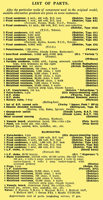
Parts list.
|