|
This is the first full description ever published of how to operate a home - constructed Cathode - Ray Television Viewer. It gives minute directions of the whole procedure necessary to 'tune-in' a broadcast television transmission - not a complicated process when using PWs specially developed simplified apparatus.
Operating the Cathode-Ray Television
In its complete form the television viewer that we have been describing will fit into a neat cabinet that will enable it to take its place in the house as a piece of furniture, just as does the radio-gramophone. But before it is packed away in the special cabinet we shall describe next week, it should be thoroughly tested and made to work properly, for nothing is more annoying than to have to dismantle an outfit of this nature after it has been carefully packed away in a cabinet.
Flexibility of Voltage
Last week we gave the full connections and the voltages required for normal. working. We, in our tests, used voltages from 350 to 800 on the cathode tube accelerator, and it must rest with the individual constructor how much potential he applies. It is useful to remember, however, that one can look upon the cathode ray tube in much the same way as an output valve - that is, the more HT it has on it the more brilliant will be the picture and the more shield modulation you can apply without distortion of the image.
The cathode tube will distort the picture in the same way as the output of a valve will be distorted if too much grid input is applied to the valve, and in the same way as with the ordinary valve, increase of anode voltage means more grid bias, so with the cathode tube increase of accelerator potential requires a necessary increase in shield bias, and of deflector bias.
All are variable, however, by either wander plugs or potentiometer control, and in the case of the shield 60 Volts maximum should be available for 350 Volts on the accelerator, and 90 Volts maximum bias if 700 to 800 Volts are used.
Protecting the Tube
For the deflectors up to 60 Volts will be required; this being variable by means of wander plugs, the bias on the shield being varied by the potentiometer control marked 1. Note that in the time-base all the potentiometers controlling bias are so wired that the bias is increased as the knobs are rotated clockwise.
The first thing to do when carrying out the preliminary operation test is to check up all the connections, seeing that not only is everything correctly connected but that all connections are really tight. Have everything connected except cathode HT plus, and the LT to the diodes and thyratrons.
Several batteries in series will have to be used for the HT supply, to the cathode-ray tube and the bias connection is tapped off so that bias positive is common with HT negative. This reduces the risk of the bias connections coming out while LT is applied.
Another safeguard against any damage being done to the tube should such an event occur is a 40,000 Ω resistance connected in series between two of the battery units forming the accelerator HT supply. We suggest that this be inserted somewhere about the middle of the whole bank of batteries.
Small 60 mA or even smaller fuses are inserted in the HT positive and the HT negative leads to the accelerator of the tube, and a micro-ammeter is used (if you have one handy) in series with the positive side.
The ammeter is in series with the LT supply, as already shown last week. A word about the LT supply. That for the thyratrons (4 Volts) can be tapped off at 2 Volts for the radio set, the negatives being common. But care must be taken that the two LT batteries feeding the diodes do not touch one another. The reason for this is that there is sufficient leakage in the battery casing to upset the action of the time-base if these two batteries are allowed to come together.
The connections to the cathode tube were shown last week, but the following hint may save much time in adjustment later on. The four deflector terminals on the tube are connected as follows. Place the tube with the anode (accelerator) pin at twelve o'clock, when the four deflector terminals, looking from the base of the tube, will take up positions corresponding to 10, 8, 4, and 2 o'clock.
Nos. 10 and 8 are adjacent, and belong one each to two pairs of deflectors in side the tube, they should be connected together and to the anode pin of the tube. No 4 should be connected to a deflector bias minus plug, and this should be inserted in that deflector bias battery that is connected at the positive end to the 0.25 μF capacitor on the time-base.
Direction of Scanning
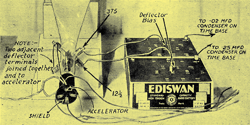
The connections to the two biased deflector plates should be particularly noted, as these are of the greatest importance it the picture is to be scanned in the right direction (i.e. from right to left).
The remaining deflector terminal No. 2 should be connected to the second deflector bias battery, whose positive goes to the 0.02 μF Capacitor on the time-base. This arrangement of connections is essential in order that the scanning shall be in the right direction, namely from bottom to top and right to left on the screen.
Now let us start to get things in operation. The set is connected up to aerial and earth and after it has been tuned-in, by means of the headphones, to the London National (this can be done before television commences) it can be switched off and left till the rest is going.
On the cathode-ray tube itself will be maker's directions as to the exact maximum filament current and this should never be exceeded, as a matter of fact, the current can be kept about 'half a point' lower for most purposes. The correct current will be about 0.9 to 1.25 Amp in all probability, but individual tubes will differ slightly. Hence the need for the meter.
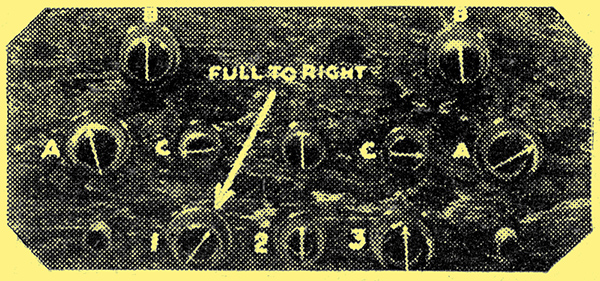
The first knob to set is Number 1.
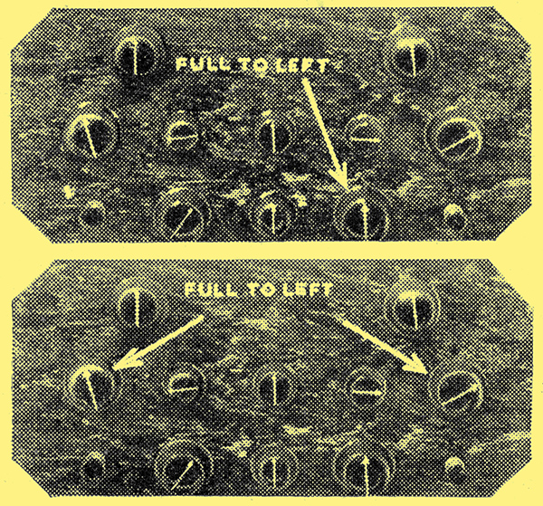
Now, with all connected up, but with cathode-ray tube HT positive switched off, and the switches on the time-base off, we can commence to set the gear in operation. First turn knob 1 hard over to the right - that gives the tube full bias as a safeguard. Then turn knob 3 hard to the left, this gives the least cathode tube filament current. Also turn knobs A and A full to the left. Set the thyratron bias at about 12 Volts, the deflector bias at about 48, and the time-base HT at 200.
Follow by adjustment of Number 3, and the two knobs marked A.
Setting Filament Current
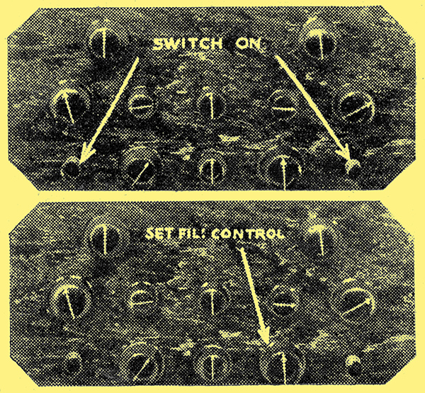
Next pull out the two switches and turn Number 3 to the right.
Next, pull out the switches on the time-base leaving the HT to the cathode-ray tube still offb. The-ammeter will begin to read, probably going to about 0.5 Amp. Increase this by turning knob 3 slowly to the right until the reading is about one point below the maker's figures. As the filament warms up this reading may increase slightly. Having checked this, reduce to about 0.5 Amp and switch on the anode potential to the cathode-ray tube. Then increase the filament again to its right value. Nothing will be seen in the tube until the shield bias is reduced. This is done by turning knob 1 very slowly to the left, watching the tube for signs of a ray on the screen all the time. Do not turn the bias control knob to more than half-way round towards the left.
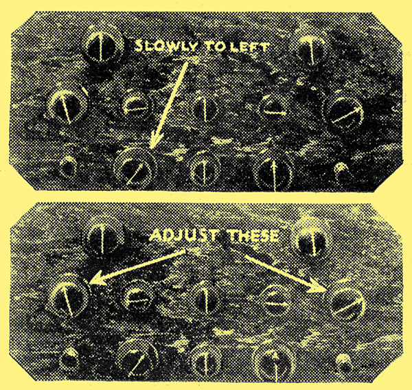
Set Number 3 for correct filament current, and adjust Number 1.
If nothing is seen at half-way round, leave the bias adjustment there and remove one of the deflector bias negative plugs; you should then see the ray flash over to one side of the screen. If not, reduce the deflector bias on both deflectors to about 9 or 12 Volts.
Finding the Spot
If you are using a micro-ammeter in the HT lead. to the cathode-ray tube it will be of great assistance, for on switching on with knob 1 to the right you will get no reading, but on decreasing the bias (turning knob to left) the reading will gradually go up. Stop the bias decrease when the micro-ammeter reads about 30 μA. At this point you have got the ray operating, but the deflector bias is such that it is not falling on the screen.
Without the micro-ammeter one has to work more in the dark, but varying the deflector bias will soon result in the light appearing on the screen. Having obtained the light spot, turn knob No. 1 to the right until the spot nearly disappears, then turn slightly to the left, and it will be found that the spot will focus to a small round circle of greenish-blue light.
We can now turn our attention to the setting of the two time-base circuits.
Knob 1 can new be left, and we can turn our attention to the setting of the time-base. Alter the bias on the deflectors until the spot is about one inch in from the right of the screen and one inch up from the foot. If it is found that the alterations of deflector bias do not move the spot either horizontally or vertically, but obliquely, the tube should be rotated on its axis until this effect is obtained.
This is to counteract the influence of the earth's magnetic field, which sometimes has a marked effect on the cathode ray. Having obtained the spot of light in the right position the thyratrons and diodes can be switched on. Being in an experimental form this can be done merely by connecting up the LT circuits, the HT being already on, there is no need for a filament switch, until the outfit is housed in its cabinet.
Being of the indirectly-heated. variety the thyratrons will take half a minute or so to heat up, and while this is taking place the two filament rheostats on the baseboard can be adjusted.
That on the right, looking from the panel end should be turned full on (to the left) while that on the right should be about two-thirds to three-quarters on. Final adjustments can be made later.
The diodes will now be alight, and on the thyratrons being hot they will commence to flash when knobs A are turned, that on the right flashing very rapidly, and the one on the left quite slowly. The speed of the flashing can be adjusted by knobs A and A.
Extent of Scanning
Turn the left-hand knob A hard to the left when it will be found, probably, that the left-hand thyratron will cease flashing. If it does not, turn the left-hand baseboard rheostat to the right until it does cease.
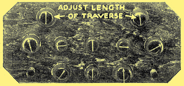
Then, if you look at the tube screen you will see that the spot of light is no longer a spot, but a line running vertically up the screen. Its length can be controlled by adjusting knob B on the right-hand group on the panel, and the length of the line should be arranged to be four inches long.
With this adjusted, turn knob A of the left-hand group, when it will be seen that the line now moves across the screen from right to left. The speed of this traverse can be adjusted by knob A, while the extent of the traverse is controlled by B of the left-hand group. Adjust this until the length of traverse is about 1⅔ inches.
The Number of Lines
Now comes the final part of the setting. We have so to arrange things that we get a framework on the screen consisting of thirty of the vertical lines travelling across the screen at the rate of 12½ complete traverses per second.
The best thing to do is to 'play about for a bit' with controls A and B in each section of the time-base, watching the effects you produce. By this means you will learn quite a lot about the action of the various controls which will be a great help later on.
You will notice that has the right-hand A knob is turned to the right the number of lines increases, while turning the left-hand knob A to the right, the rapidity with which the lines travel to the left is increased.
It may be found that the lines are a bit fuzzy, if so, adjust knob 1 very carefully until they are sharp, commencing the adjustment by turning fully to the right, when the lines will vanish and then slowly to the left until sharpness is reached. You will notice, if you use a micro-ammeter that as the knob 1 is rotated to the left the reading on the meter gradually increases. It must never be allowed to exceed 40 to 50 μA.
Now adjust knob A of the right-hand group until you can count thirty lines. Keep the length of the lines 4 in all the time. The next task is to check up the speed of the right to left movement, so that it is exactly 12½ times per second. This is not so easy unless you have handy either AC or a constant frequency record of 50 Hz.
A Test Frequency
If you have either of these you can apply 50 Hz modulation to the time base through a pick-up adaptor inserted in V3 of the radio set. Only a weak modulation need be used, and the AC from the mains can be applied via a 4 Volt LT transformer of the usual mains type through a couple of capacitors.
In the event of this test being available you will see that the luminous portion of the cathode-ray screen will be broken up into black bands running vertically. The knob A on the left should then be adjusted until the bands number four, and remain fairly steady in position. Note, all the time you must readjust the right-hand knob A to retain thirty lines on the screen.
If this test is not available we must proceed without it to try the set on actual television. Make sure of the thirty lines, however, for it will not be difficult to get the right scanning speed of 12½ per second if these lines are correct. It must be realised, however, that adjustment of the 12½ side will throw out the number of lines a little.
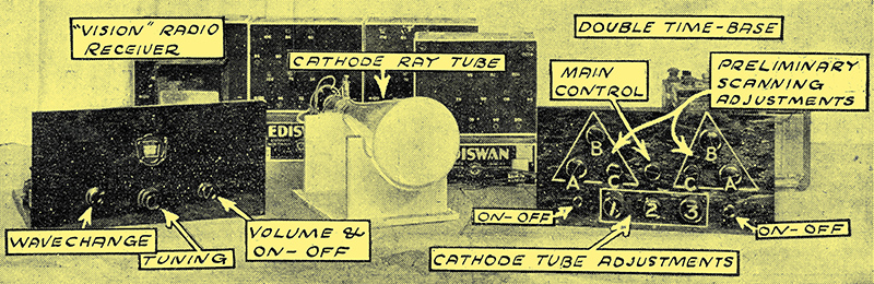
For television the radio set is used, connected as shown in last week's diagram. The station should be tuned fairly fully in, and then the strength of the output applied to the time base is separately controlled by knobs C and C, and by the central control. The strength of the impulses given to the cathode-ray tube is controlled by knob 2.
Lines Broken Up
With television on you will notice that the lines on the cathode-ray tube are broken up by splashes of black. These can gradually be resolved into black horizontal bands by the adjustment of the knobs marked A, especially the right-hand one. Do not worry about what happens to the length and breadth of the picture at first, but slowly adjust these knobs until you get the black bands, fairly thick ones, running horizontally.
Then by further adjustment of knob A on the right, you should be able to get rough images on the screen. You will notice, however, that sometimes these images will suddenly start to run up or down off the screen. This means the viewer is out of synchronism. Adjustment of knobs C should help to stop that, with final control being exercised by the centre knob on the time-base panel.
You must not expect to get things going exactly right first time, the handling of the television viewer will come after practice, and you will then be able to switch on just before a broadcast and get everything with ease.
We shall be glad to answer any question concerning the viewer, for it is a quite new technique in radio reception, and there is quite a lot to get used to. Messrs. Ediswan, too, will be glad to lend any assistance in their power on the subject.
Final Control
When the television viewer is operating properly, it will be found that the synchronising of the pictures can be adjusted by at slight turn of the centre knob, with perhaps & little adjustment of the two C knobs, which control the strength of the synchronising impulses.
The modulation of the cathode-ray tube is controlled by the knob marked 2, and this should be turned to the right as far as it will go without the picture becoming 'frayed' at the ends or wrinkled denoting that the tube is being over modulated.
The last step of all is to re-focus the picture by means of the knob 1. This re-focusing will need only slight adjustment, and for best results the picture should not be so sharply focused as to be broken up into its component vertical lines.
Once set all these adjustments can be left, and the viewer is ready for use at anytime a. transmission is in progress, slight control of the synchronism being necessary.
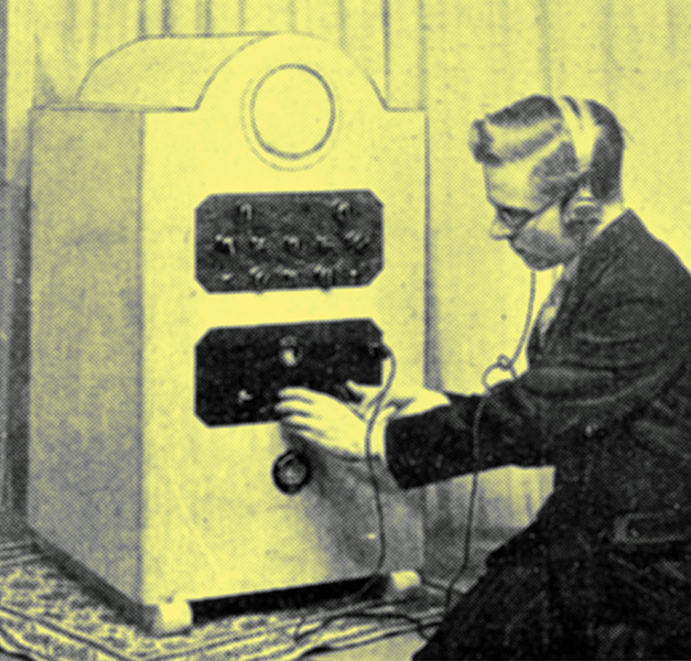
Tuning the vision receiver in the complete Cathode-Ray Television outfit. The special cabinet shown will be described next week.
Return to series start
|