|
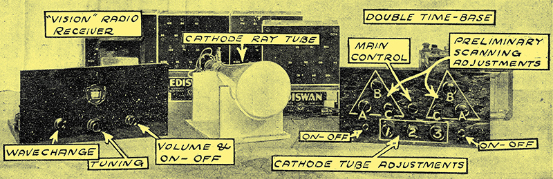
The complete receiver.
Continuing the description of our inexpensive and easy - to - make cathode ray television viewer, full details are given this week of a special set for the reception of 'vision' broadcasts. This set is both economical to run and simple to operate.
The Vision Receiver
The receiver supplies the synchronising pulses as well as those for light modulation. And for this reason parallel output valves are used, each performing one of these duties.
The two previous articles have dealt with the methods employed in our cathode ray television viewer for scanning and controlling the electron beam emitted by the tube. And the simple nature of the assembly of components required to do this has been made apparent.
It now remains to go into the matter of the radio receiver that is to pick up the broadcast pictures, and then to assemble the units of the viewer to form the composite instrument.
The radio receiver is extremely simple, and those who do not wish to build it in toto will be able to convert their existing receivers quite easily. But before I embark on the description of the actual set used in the Research Department in conjunction with the time-base already described, I should like to express my deep regret that the BBC do not give more facilities to reception research by giving longer television broadcasts. Half-hour spasms four times a week are not much use to the research engineer; and longer periods would be most valuable.
Important Discovery
But, in spite of the restraint placed on research by the BBC, we have managed to carry out a considerable amount of investigation - largely in half-hour doses, of course, late at night and the results so far attained we are presenting for your notice.
One of the most important things we have found out is that control of synchronisation in the cathode ray scheme can be carried out by impulses of a fraction of a Volt, provided they are clear of extraneous potentials.
The main synchronising impulse is that which comes over at 375 times a second; that is the one that marks the commencement of each vertical scanning line, there being 30 lines 12½ times per second.
The other synchronising impulse which controls the speed of the picture-change, i.e. the number of complete scans per second is the 12½ per sec. impulse, and this is not nearly so important.
Cumulative Effect
To assist in the production of this latter impulse strongly enough the two thyratrons of the double time-base described in the previous article are linked. This is done in such a way that the thyratron flashing at 375 impulses per second passes the 375 per sec. flash impulses to the grid of the 12½ valve.
These impulses are not strong enough to upset the 12½ valve, but this valve is also receiving from the radio set a certain proportion of the 12½ synchronising impulse sent out. It may be weak, but when on it is superimposed one of the 375 'kicks' the cumulative effect is noticeable, and we get real benefit from it.
Naturally, both thyratrons get 375 + 12½ impulses, the latter very weakly owing to the difficulty of reproducing 12½ through any radio set, but the impulses need not be strong, as will be seen.
One thyratron is flashing at a normal set speed of round about 375, and the other is flashing at 12½ per second. These frequencies can be obtained quite easily by hand adjustment of the two controls marked A (see last previous article).
Adjusting Scanning Speed
The main thing is not to obtain the speeds, but to keep them. Now, as you will find if you experiment with your time-base, the grid-bias adjustment of the thyratrons not only has the effect of varying the length of the traverse of the beam (you will see this later) but it also affects the speed of scanning.
These two effects are due to the same cause, variation of the thyratron impedance by bias variation, and therefore variation of the voltage at which the mercury discharge takes place.
New then. We have a steady static bias on the thyratron grids, and with that bias fixed we adjust the speed of the diode feed to the fixed capacitors so that the requisite flashover voltage for the thyratrons is reached 375 and 12½ times per second respectively.
Any bias alteration will throw these speeds out unless further diode adjustment is made to counteract it. But suppose we set the bias-cum-diode adjustments in such a way that the 375 thyratron is running very slightly slow (due to too much bias), say, for example, 374.5 per second, Then the arrival at 375 of a positive impulse on the grid would just trigger the valve and the flash would come dead on time. Similarly, if the valve is going 'fast' (due to a fraction too little bias) a negative impulse would just hold it back so that it flashed at the right time.
Dual Outputs
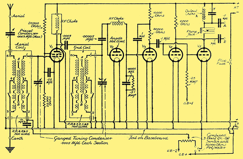
The receiver has a multi-mu HF valve followed by a diode detector, and uses resistance-capacity coupling. X and Y denote the special tuned output filter mentioned in the text.
This is the theory and practice employed for the synchronising of both thyratrons, 375 per second being used in one case and 12½ in the other. There is one snag which we have to overcome - the obviously bad effect of the normal television modulation, which is variable, being applied to the thyratron grids.
A sudden big modulation impulse applied to the 375 thyratron grid is quite enough to upset the time period of the flashes, and so these come at the beginning of the scanning lines and so they do not upset the picture at ail.
The other output is provided by a parallel valve with a tuned filter feed output circuit. This is marked X and Y in the diagrams shown here, and we are still carrying out experiments with the constants of the circuit, in order to get as low a decrement (steep resonance) as possible.
So far the best results have been obtained with a choke of 0.8 Henry (specially low resistance wound by RI, and obtainable from them to individual order) tuned by a 0.25 μF capacitor. This resonates at 375 Hz, and the curve shows quite a good decrement. The result is that there is a very much greater output for this valve of frequencies round 375 than any other frequencies.
Separately Controllable
Apply this output to the synchronising circuit of the time-base and we have a fairly clean 375 series of impulses. Modulation is much reduced so that the unwanted 'tripping' effect of the picture frequencies is practically eliminated.
We could use a third valve and tune for 12½ per second so that we got the maximum possible 12½ synchronising impulse, but this does not seem to be necessary. The 12½ thyratron keeps steadily flashing without much need of automatic control and the small amount of 12½ augmented by the 375 which is passed on from the anode of the other valve, seems to do the trick.
The strengths of both modulation and synchronising are separately controllable on the time-base by knob '2' in the first case, and the centre knob (main control) in the second.
Built for Quality
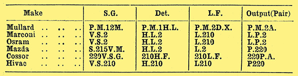
Recommended valves.
So much for the output side of the radio set. The rest of the receiver built on 'quality' lines, for distortion due to non-linear response in the receiver is fatal to good picture reception, the result being bad picture distortion.
It cannot be too strongly stressed how important it is that the radio receiver shall be reasonably straight-line in amplification, and that it shall be free from any trace of valve overloading.
Detector overloading is one of the greatest bugbears in television reception - it shows up horribly on the screen, much more than in the speaker when music is being reproduced - and the cathode ray is very sensitive to any form of modulation distortion.
The diode type of rectifier has been chosen in our receiver as giving the best form of rectification, for it is free from the overloading bogey, and provides at wonderfully distortion-less output.
Following the diode is an LF stage resistance coupled to the split output stage already mentioned. To provide adequate input to the rectifier, and to arrange for satisfactory volume control of the radio receiver, a multiμ HF stage is used.
The tuning is carried out by plain inductances so that the selectivity is sufficiently broad to prevent sideband cut off, with its deleterious effect on the picture reception, while it is sufficient to prevent interference from nearby stations.
Avoiding Negative Pictures
In the design of a television receiver care has to be taken that the right phase relationship is obtained, for it is just as easy to obtain a negative picture as it is to get a positive one.
This peculiarity is synonymous with the negative and positive as applied to photography, and a negative television picture reproduces the light portions as dark ones, and vice versa. To prevent this the number of LF stages must be correct, for each stage reverses the phase of the received impulses, so that we get alternately positive and negative pictures as we go from stage to stage through the receiver after the rectifier.
Here, too, the type of rectifier must be taken into account, for the leaky-grid type results in a negative picture, and the diode in a positive one. Therefore if leaky-grid rectification is used the set must have either one or three LF stages of amplification if a positive out-put is to be obtained, while the diode requires either two or four stages following for the same result.
Low Power Requirements
In the cathode ray system of reception the amplification required is not great, for, as previously stated, the cathode tube is a voltage-operated device, and so a mere few volts (about 5 Volts RMS) are required to modulate the tube fully.
In the case of the glow-lamp type of light supply quite a large power is required, a matter of watts AC output being necessary for good modulation of the light source, resulting in the need for great modulation and large valves.
This is a point that cannot be stressed to much, for whereas in the cathode ray system small battery operated valves with a mere 120 Volts HT give ample output, the mechanical method of reception necessitates mains valves and heavy anode power consumption if bright pictures are to be obtained.
The relative consumptions of the receivers for the two systems works out at something like 120 Volts and 10 milliamps for cathode ray work, and 250 to 400 Volts and round about 50 milliamps for satisfactory reception on other systems.
Obviously, then, the cathode ray scheme scores very heavily on this point, as it does on the other features that have already been brought to your notice.
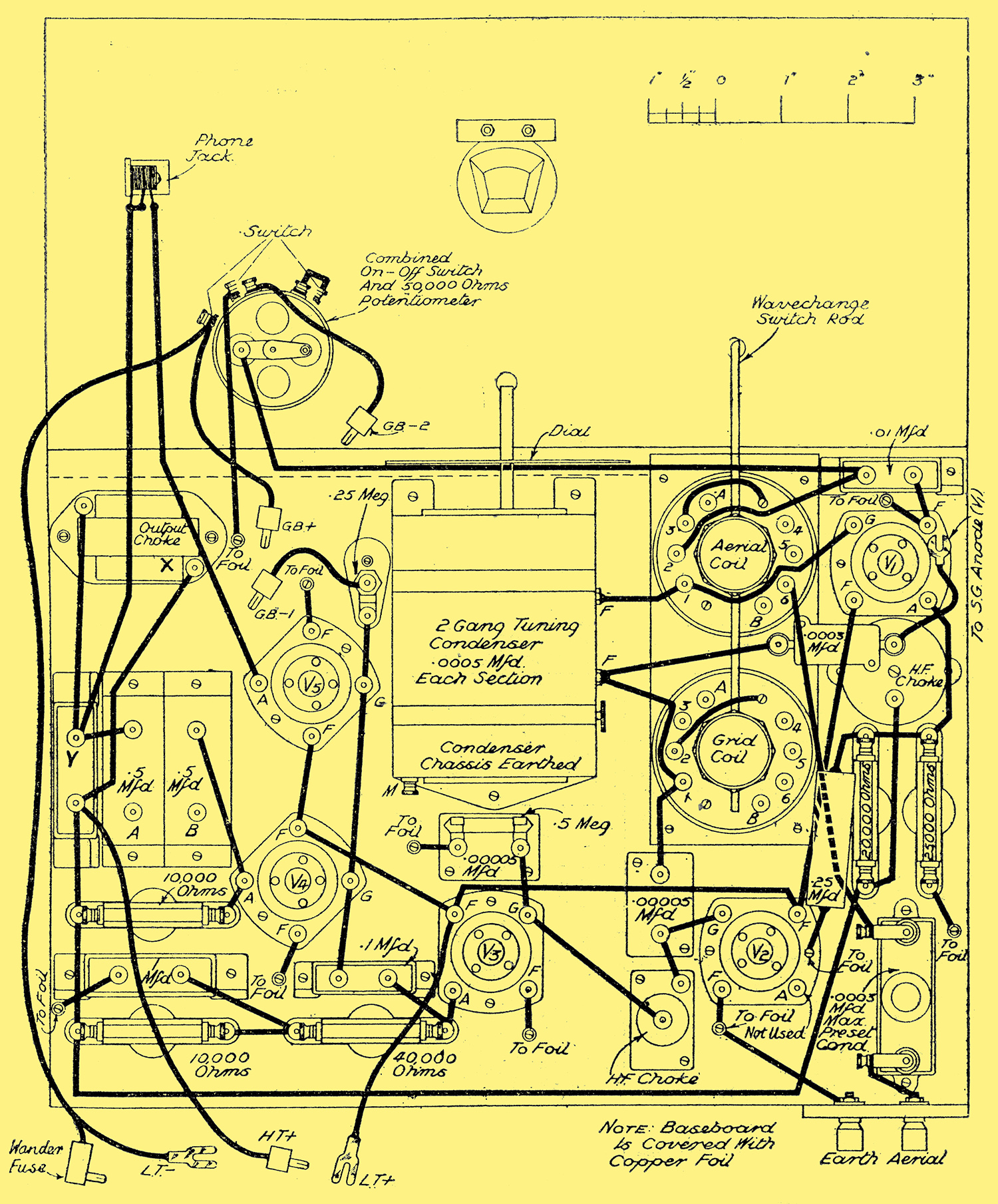
The actual constructional facts of the cathode my receiver are so simple that we need not go into them in detail. The photographs and diagrams show very clearly how construction is carried out, and the set is obviously as easy to make as an ordinary small broadcast set.
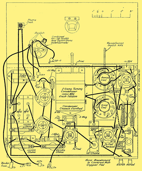
All the wiring is shown in this diagram, and the special tuned output filter 375 synchronising pulse comprises the choke X and the capacitor Y its object is to prevent strong modulation from upsetting the flash point of the two thyratron valves.
It is built on normal baseboard lines, and offers no difficulties either in construction and operation. Single-dial tuning control with concentric trimming is employed for wavelength adjustment, and long waves have been incorporated, because although in this country all present television transmissions are carried out on the London National there are transmissions available from the long-wave Berlin station that will be of interest to experimenters.
An Aid to Tuning
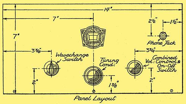
Only three knobs to turn.
No reaction is used, as this is a frequent source of distortion where vision reception is concerned, While a plug and jack break is inserted in the synchronising output circuit so that a pair of phones maybe inserted while the set is being tuned in. This is a valuable feature, for it enables accurate aural tuning to be carried out without any interference with the modulation of the cathode tube.
The rigging up of the set will be discussed later, When the complete Television Viewer is assembled. but it can be seen from the foregoing that this is a very easy matter.
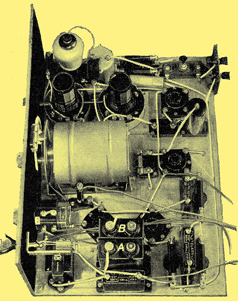
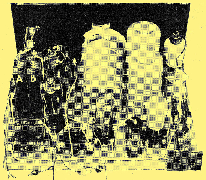
One of the features of our Television Viewer is its suitability for many systems. The letters A and B against the blank capacitor terminals in the photograph indicate the two output points similarly marked A and B in the theoretical diagram. These points connect with the wires similarly marked on the time-base described previously.
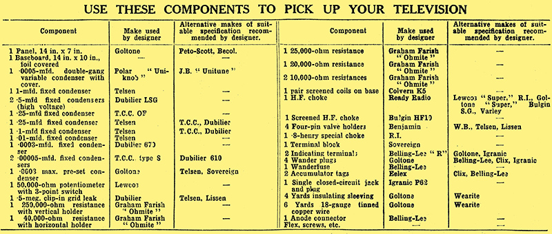
The vision receiver components list.
Return to series start
|