|
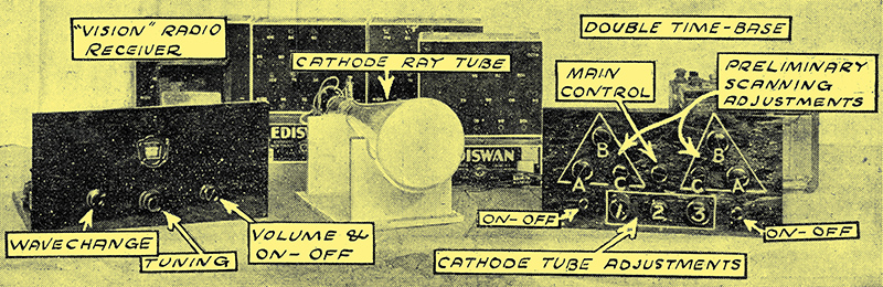
The complete receiver.
Double Time Base Unit
As a start we are going to describe the building of the double time-base unit, the section of the gear that causes the beam in the cathode tube to carry out even, and perfectly controlled, scanning. But before we do that we should like you to get a good grasp of what will be necessary in order to assemble the complete viewer.
We have mentioned the double timebase the component list of which is given herein and the possession of a cathode ray tube, Ediswan type T, is a foregone conclusion.
In addition a small radio set is required. This can be a three or four valver of quite modest design, but, to make it most effective for picture reception it should have resistance coupling, and a special, quite cheap filter output circuit.
This set can easily be knocked up out of components you have by you - you will want your ordinary set for the sound reception on another wavelength, so you cannot use that set for vision - but as a guide we are going to publish details of a suitable battery set.
The significance of the various groups of controls A, B, C; C, B, A and 1, 2, 3 are explained.
The Power Supply
All that remains is the power to operate the tube, the time-base and the radio receiver. This is going to sound a great deal, but it is not so much as it sounds, for it must be noted that the cathode ray tube, requiring as it does a rather high HT voltage (from 350 Volts upwards) on its accelerator, does not consume any HT current worth talking about. The current consumption is as mere 20-30 μA. So the HT batteries, which can be of the smallest capacity dry type, have a life similar to their life in the hands of the radio dealer - i.e. their shelf life.
Sundry other battery supplies are necessary, HT for the timebase and the receiver, and bias for the cathode tube shield (which is tapped off the accelerator HT), and for the deflectors. In all the reception of television can be carried out with at total voltage of 700 Volts or so, split up into sections among the different parts of the apparatus.
But as the current taken from this supply is very small indeed, the wattage consumption is extremely small, and compares most favourably with the large wattage needed for the operation of the mechanical methods.
No Danger
There is no danger of serious shock with the cathode ray scheme if proper precautions are taken, for in the HT supply to the tube (350 Volts or so - it can be increased to 700 if desired), a low-milliamp fuse can be inserted to prevent heavy current flow, or a resistance can be used in series for the same reason.
Moreover, in our finished design, as you will see, We have taken ample precautions to protect the operator from inadvertent shocks, not that they would be likely to be harmful if received, but because none of us likes electric shocks, however mild. The LT supply consists of five 2 Volt cells, supplying the whole of the outfit with LT current.
Certain sections could be mains operated, but the risk of LF interference is rather large, and any superimposition of AC ripple on the cathode tube modulation ruins reception. This trouble we hope shortly to overcome, however.
So far we have said nothing about the obtaining of varying degrees of light on the screen, though we have seen how the cathode ray can be swept up and down, and across, the tube to provide the requisite scanning.
Effect of Negative Bias
It has, however, been pointed out that negative bias on the shield of the tube (Fig. 1.) will cause the electrons from the cathode to be squeezed together so that they go through the hole in the accelerator in a concentrated beam. Without that focusing, as it is called, a lot of the electrons would spring off the cathode straight on to the accelerator, and would not go through the hole in it.
The accelerator attracts the electrons very strongly, and they are all trying to get to the accelerator plate, which, like the anode of an ordinary valve, would allow them to flow back externally to the LT battery, whence they originally came to cathode.
The Beam
But by focusing the beam we get the electrons flying at a tremendous rate towards the hole in the accelerator, being attracted by the positive potential on the accelerator. The electrons do not want to go through the hole - they want to get to the accelerator - but they are going too fast. They can't pull up, and so they shoot through the hole and right up the tube to the screen.
With them go protons, vainly trying to get into the electron stream, and these protons, forming a cloud round the electrons help to keep the beam closely knit.
Electrons Produce Fluorescence
On reaching the screen the electrons cause the Willemite or calcium tungstate, of which the screen coating is made, to fluoresce and we get our light. The spent electrons then leave the screen and, their speed checked, they fly back to the accelerator.
By altering the bias on the shield round the cathode we can vary the concentration of the beam, and with the aid of a potentiometer bias control we can get the beam to produce sharply defined tracings on the screen - in other words we achieve focusing.
Now if we increase the bias to values above those required for focusing we begin to cut off the number of electrons leaving the cathode, in the same way as we reduce them to an ordinary valve by increasing grid bias. And as we reduce the number so does the light from the screen diminish.
Light Easily Cut Off
And it does not require much bias increase to result in a complete cut-oft of electrons - no light from the screen. Obviously, then, we can apply LF inputs to the shield in such a way that they modulate the bias voltage, in the same way as modulations are applied to the grid of a valve. This application to the cathode ray tube should result in a variation of the number of electrons in accordance with the LF impulses applied.
This does happen, and the result is varying light from the screen - in other words, light modulation, just what we require for television reception
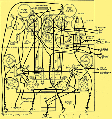
We give the theoretical and wiring diagrams for the four valve piece of apparatus known as a double timebase. It is this device that is used to swing the cathode ray about to make it scan the screen.
Half the timebase causes the beam to run vertically up the screen, and the other half to move across from left to right. The result is 30 scanning lines vertically carried out 12½ times per second. That is what is required by the Baird process of television transmission.
We saw that the scanning effect could be obtained with a resistance, capacitor and glow-discharge tube. In practice this is more accurately obtained with a diode instead of the resistance, with the capacitor as before, and at thyratron type of glow discharge tube.
By these means we get a complete control of the time taken for the scanning to be carried out, and the distance of travel of the cathode ray before it completes the scanning and is returned instantaneously, by the discharge of the capacitor by the glow tube.
The input voltage across the capacitor is fixed, and the size of the capacitor in each timebase section is fixed. The variation of the time taken for the capacitor to charge up is obtained by controlling the filament heat of the diode valve, by means of an ordinary rheostat. Thus we can feed current into the capacitor at a regular and predetermined rate.
Predetermined Flash Voltage
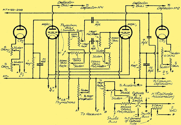
The double timebase circuit used to carry out scanning and synchronisation.
By applying bias to the grids of the thyratrons, we can also predetermine the voltage at which they will flash over and discharge the capacitors. Thus we have complete control over the time of the scanning of the beam. How this is used in practice we shall describe later.
If you study the circuity given (it differs slightly in some minor features from the one given before) you will see that the two timebases each contain a diode valve (Ediswan CR2) and a thyratron (Ediswan MR/AC1). In addition, from anode to cathode of each thyratron is a capacitor across which is a resistance. These capacitors are vital parts of the circuits, for they are the capacitors that have to be charged and then suddenly discharged by the thyratrons.
Discharge Rates
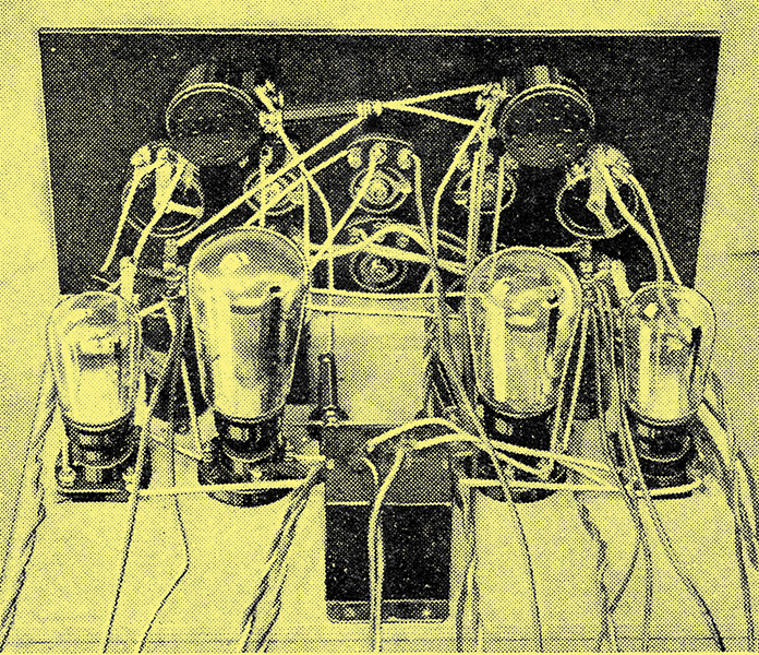
The two outside small valves are the diodes for regulating the current flow, the larger ones being the thyratron mercury-vapour discharge tubes.
In one case the value of the capacitor is 0.25 μF, and in the other it is 0.02 μF. This is because the first has to charge and discharge at a slower rate than the second, the actual rates being controlled as before mentioned, but being set by means of the natural characteristics of the circuit somewhere near the required figure.
Actually the 0.25 μF capacitor has to charge and discharge at 12½ times at second, while the other has to work at 30 times that speed.
The resistances in series with the filaments of the diodes are for 'coarse' and 'fine' adjustments, and the 6 Ω coarse ones are situated on the base-board behind the panel, for after they are set there is no need to touch them again. As a matter of fact, the same can be said of a number of the knobs on the panel, for many are of the once-set-left-alone type, though it is handy to have them on the panel in case any slight departure from adjustment of the apparatus is noticed.
The actual construction of the timebase is extremely simple and can be carried out in a very short time. Rather a lot of flex leads are used to connect the timebase to the batteries and the cathode ray tube, but these are considered more satisfactory than terminals, for flex leads can be made more secure to their sources if they are tightly fixed when the set is built than can leads taken to ordinary terminals.
In the diagram of the theoretical circuit we have given all the main connections to the timebase, and to the cathode ray tube as well. These show how the whole outfit is connected, including the output from the radio receiver, but we propose to complete the construction of every part before we go on to their operation, and to the linking of the various parts together, and so the full use of the diagram will be made later.
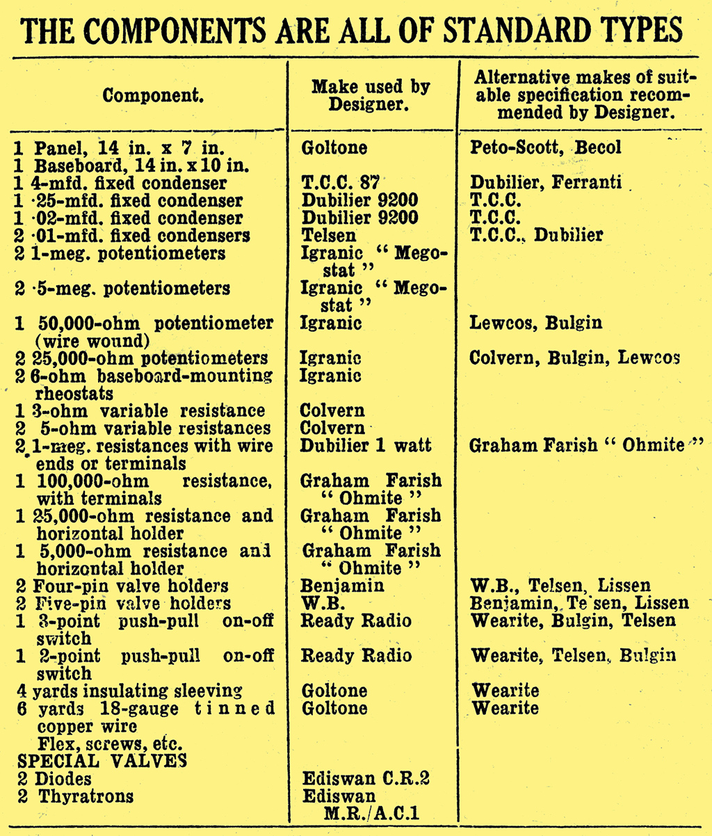
All parts used in the timebase should be of good, reliable manufacture, and constructors are strongly advised to keep to the makes specified in the list given below. The values, too, are critical and should not be altered on any account.
Indirectly Heated Valves
The thyratrons are indirectly heated valves, and are operated by a common 4 Volt LT supply. In the case of the diodes, which are of the directly heated filament type, a separate 2 Volt battery must be used for each.
The question of the battery controls for the thyratrons and the diodes will come up later when the whole assembly of the system is considered, for we suggest that a battery box, containing HT and LT compartments, be used with the requisite control switches on it.
The cathode-ray tube can be controlled by the switch on the panel of the time-base, for as it is essential to provide the tube with a shield battery switch, it was considered best to kill two birds with one stone and to control the filament with the same switch.
Testing the Timebase
A large proportion of the wiring is carried out with flex. But the stiff wires are best fitted in place first, for convenience in building.
When the timebase has been built, it should be tested in part to see the filaments are correctly connected, and that the diode filaments can be controlled by the resistances. If you care to connect 150 to 200 Volts to HT plus and minus, and to connect two 2 Volt LT batteries to the diode inputs, and a 4 Volt supply to the thyratrons you will be able to see the latter in action. flashing over at different intervals as the diode resistances are varied, and the rate of charge and discharge is controlled.
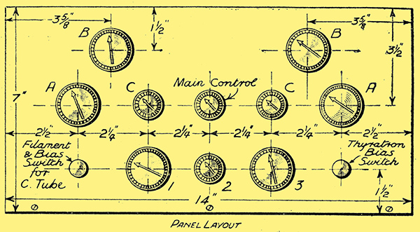
About 9 Volts grid bias will be required on the thyratrons, and the potentiometers controlling this bias (marked B in the front of panel diagram and photograph) should be about central.
Turn the right-hand (looking at it from front of panel) baseboard-mounted rheostat full on, and control the diode it refers to by the panel rheostat only (A on the right- hand side). The left-hand baseboard rheostat should be about ¾ on, and control of its diode carried out by A on the left of the panel.
Two Complete Sections
Note in this case especially how the speed of the blue glow of the thyratron is varied. You will have seen that the timebase is divided into two complete, but linked, sections, the left-hand part (from front) being the 12½ and the right hand the 375 per sec.
You will find that at this stage none of the other controls make any difference, for they all refer to the actual scanning on the cathode tube, and their effects can only be seen when the tube is connected up.
But as a rough test of the timebase the foregoing is useful, especially if it is remembered that the right-hand thyratron will light up continuously (or so it seems, for the 375 flashes per second are not separately visible), while the left-hand one distinctly flashes at a very much slower rate, according to the diode control setting.
Obtaining a 'Tick Over
If the timebase is working really well, and the diode control of the right hand section is carefully set, it may be possible by judicious variation of the bias control (B) to make the 375 thyratron 'tick over' slowly, or comparatively slowly. But this is not important, and it is not a sign, that everything is OK unless the rapid flash giving apparently continuous discharge is alternatively obtainable.
If you, cannot control the timebase suspect the 0.25- and 0.02 μF capacitors, or the resistances across them. Leakage here, at a greater rate than required, due to faulty capacitors or resistances, will completely upset the operation of the circuit. So much for the construction and preliminary tests of the timebase for the cathode ray television viewer.
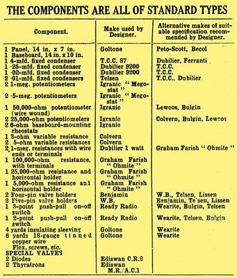
Components list.
Return to series start
|