|
Fascinating facts about a Television method that is quite independent revolving discs.
Recent developments in television, particularly in America and Germany, show a distinct swing of the pendulum in favour of using cathode rays as a substitute for rotating discs. The cost of a cathode-ray receiver, for instance, need be no higher than that of a set using a motor-driven scanning disc, whilst it has the definite advantage of producing a picture which is automatically framed on the viewing screen and is noticeably free from flicker.
The Method Employed
The method of controlling the electron stream by the grids which it parses will be evident from these diagrams.
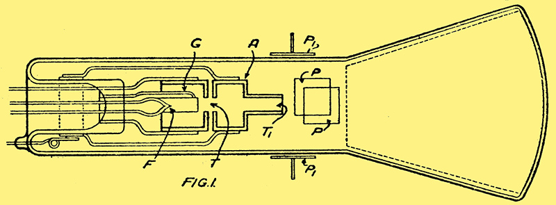
In the Zworykin tube shown in Fig. 1 electrons emitted from an oxide-coated filament F are accelerated by the positive voltage on the anode A into a fast-moving stream, which is reduced to a fine pencil by being passed in succession through two small apertures T, T1. In this form it is swept to and fro over a fluorescent coating on the enlarged end of the tube. At each point of impact the pencil produces a visible spot of light, the intensity of which depends upon the density of the stream or the number of electrons which strike any particular point on the screen. This, in turn, is controlled by the incoming picture signals which are applied to a control grid G, so as to divert more or less of the electrons away from the apertures T, T1.
No Moving Parts
Provided that the to-and-fro movement of the electron pencil over the fluorescent screen is properly synchronised with the transmitter, the original picture will be seen in greenish light-and-shade on the end wall of the receiving tube.
Synchronisation involves no mechanically moving parts. A wave of the required frequency, superimposed on the radiated picture signals, is applied to a pair of plates P arranged inside the tube so as to swing the electron pencil rapidly to and fro across the fluorescent screen. A lower frequency is applied to another pair of plates P1, in order the deflect the pencil gradually downwards from top to bottom of the screen. This second frequency is derived locally from a capacitor which has a definite period of discharge.
Controlling the Electron Speed
The result of the combined movements is to cause the electron. pencil to traverse every point on the viewing screen from twelve to fourteen times a second. In other words, the complete picture is repeated at this rate, and the persistence of vision does the effect of motion.
As previously explained,the incoming picture signals are applied to increase or diminish the number of the electrons falling on the viewing screen, thereby varying the light and shade effects.
It is also possible to secure the necessary variations in light and shade by regulating the velocity of impact of the electrons on the fluorescent screen. The higher the speed at which an electron strikes against the fluorescent coating, the greater the intensity of light it will produce, and vice-versa.
The pull of the control grids (G) regulates the degree of light or shade.
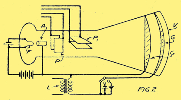
For instance, in the arrangement shown in Fig. 2 the control grid G, to which the incoming signals are applied from the input L, is located near the far end of the bulb, i.e. close to the actual viewing screen V. In this way the grid voltages serve to increase or diminish the speed of the electrons; and therefore the force of their impact upon the viewing screen. It will be noticed that this is done without in any way interfering with the scanning movement applied by the synchronising plates P, P1.
A Space Charge Effect
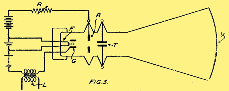
Fig. 3.
A third method, illustrated in Fig. 3, is to apply the incoming signals from an input L to a negatively-biased cylindrical electrode G, which surrounds the filament F. The resulting field from the cylinder varies the bspace charge or cloud of electrons normally formed near the cathode and in so doing alters the density of the electron emission. This, in turn, produces corresponding light and shade effects on the viewing screenbV.
In order to prevent the signal voltages from simultaneously affecting the speed of the electrons - as well as their number - the voltage applied to the anode A is varied at the same time as, but in opposite phase to, the signal voltages by inserting a resistance R in the external anode circuit. When the incoming picture signals correspond to a point of high light intensity (i.e. to a positive grid voltage) the resulting potential drop along the resistance R simultaneously reduces the anode voltage, so that the total accelerating force on the electron stream is kept constant. When a dark spot comes through on to the grid, i.e, when the voltage swing is negative, the anode potential is at its maximum. In this way an approximately steady electron velocity is maintained at all times.
The Farnsworth Tube
In the Farnsworth cathode-ray transmitter the picture is focused as a whole upon a photo-electric plate forming the cathode of the tube, and the resulting electron emission from the cathode carries the picture within itself, so to speak, along the whole length of the tube. That is to say, if a fluorescent screen were interposed at any point along the electron stream, the original image would be reproduced upon it.
This alignment of the picture along the stream is ensured by means of a strong magnetic field which maintains each electron in its proper position as the whole stream moves along the tube relative movement of the electrons would, of course, cause the picture to become blurred. At the far end of the tube the picture carried by the stream is swung by the magnetic control field to and fro, and up and down, past a central aperture in a screen. Electrons passing through the screen fall on to a target anode, where they set up current variations corresponding to, the light and dark areas of the original picture.
Moved Bodily
This is a reversal of the usual method of scanning. Instead of exploring a stationary picture by a moving spot of light, the picture in the Farnsworth transmitter is moved bodily past a stationary aperture, through which the various parts of the picture are thrown in rapid succession. The tube used by Farnsworth in reception operates in much the same away as the Zworykin tube already described.
A common problem in all television systems arises from the fact that the amount of light available for scanning is usually too small to produce an adequate response from the photo-electric cell. One possible remedy is, of course to increase the sensitivity of the cell for a given intensity of light, but there is a limit to what can be done, in this direction.
Another possibility is to amplify the intensity of the light, normally available after reflection from the scanned image Even when the scanning ray is made as strong as possible, the reflected light is always a mere fraction of the original, and its effect on a photo-electric cell is correspondingly weak.
A Light Amplifier
This arrangement can be applied at either the sending or receiving end.
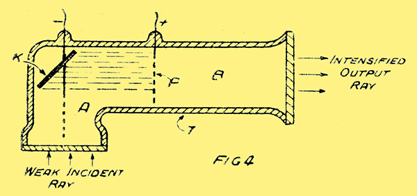
The arrangement illustrated in Fig. 4 is designed to amplify the intensity of a given ray of light, either after reflection from the picture being scanned or when reproducing a picture at the receiving end.
The light amplifier tube T is separated by a thin metal-foil plate P into two chambers A, B. The part A is highly exhausted and contains a photo electric cathode whilst the part B is filled with low-pressure gas.
The light ray to be intensified enters the tube as shown by the arrow and, falling on, the photo-electric cathode K, produces a stream of electrons which are attracted to the positively-charged plate P. The plate is sufficiently thin to allow the electrons to pass through into the gaseous chamber, where they immediately create a glow-discharge many times stronger than the original ray. The light so amplified is applied either to a photo-electric cell or is thrown directly on to a viewing screen.
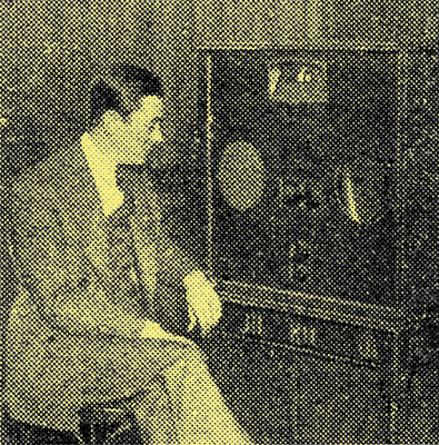 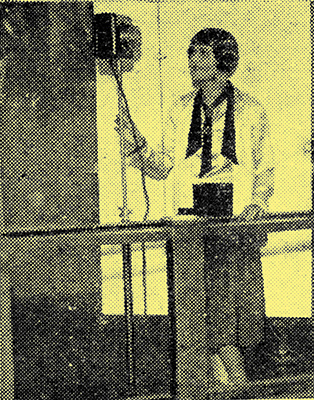
Two pictures presented with the paper.
|