|
Most readers with a elementary knowledge of sound transmission and reception will find in this article the supplementary information necessary for an understanding of the functioning of television. The subjects dealt with include the necessity for scanning, the method of synchronising pictures and the functioning of the Emitron camera.
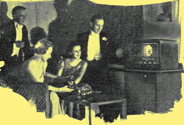
The cathode-ray tube receiver.Click here for a CRT of the time.
The present high standard of television is not, as some people seem to think, the result of some new fundamental scientific discovery. The cause for wonder lies rather in the ingenuity with which so many known physical phenomena have been brought together into a workable scheme, remarkable alike for its reliability and refinement of performance.
Between the aerials of the television transmitter and receiver the electrical impulses equivalent to vision do not differ essentially from those which carry sound. They manifest themselves as variations in the strength (modulation) of a wireless wave of fixed wavelength, and can be detected and reduced to a form capable of producing fluctuating light by receivers similar to those which produce the currents in the loud speaker of a broadcast set.
In the studio, light from the subject is allowed to fall on a substance such as potassium or caesium, which has the property of liberating electrons under the influence of light in the same way that the filament of a valve gives off electrons when heated. Collected together, these electrons form a current which, when amplified, may be used to modulate the transmitter.
Electricity into Light
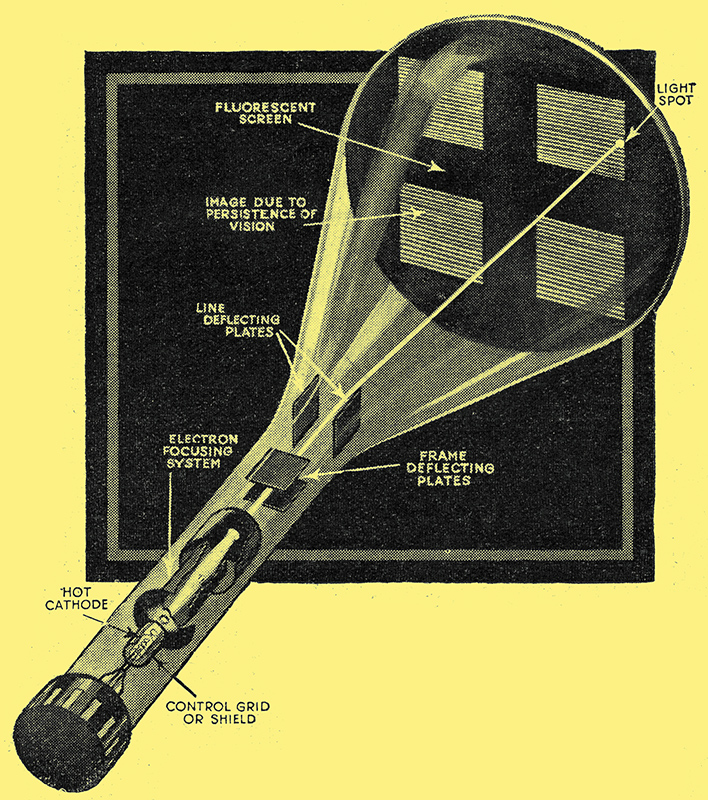
Electrons given off in excess by the hot cathode are liberated through a hole in the shield or grid in quantities proportional to the voltage signal, which is applied to this grid. They are then focused into a narrow beam by the electrode system and impinge on the fluorescent coating on the end of the tube to forma brilliant spot of light. The pairs of parallel plates at right angles to each other are supplied with voltages from the frame and line time bases which cause the spot to scan the fluorescent screen from left to right in successive lines from top to bottom of the picture.
At the receiving end the equivalent change of current could be reconverted into light by the filament of a lamp or a neon tube, but for television a more sensitive method is employed. It is the converse of that manifested in the photo-electric cell. The substance used for coating the end of the television tube is one which gives off light when bombarded by electrons. The stream of electrons (cathode rays) for this purpose is produced by a valve filament. The electrons can be increased or decreased in strength, crowded into a narrow pencil and deflected from side to side by the attraction or repulsion of suitably placed electrodes or magnets. The intensity of light on the screen is, in fact, governed by applying the modulation in the wave coming from the television station to the grid of the cathode-ray tube.
By these means we can faithfully re-produce a rise or fall in the intensity of light at the studio, but that is very far from being able to see in detail what is actually taking place there. If we were to focus a sharp image of the scene on the plate of the photocell, all that would be registered at the other end would be the average illumination; we should be able to tell, for instance, when some of the floodlights were turned off or when the station closed down for the night.
The simplest way of sending a picture, simplest, that is to say, in principle, would be to throw an image of the scene on a screen built up of a number of photocells, each with its own transmitter tuned to a slightly different wavelength from its neighbours. At the receiving end there would be a similar number of receiving sets, each with its lamp, neon tube or cathode-ray tube grouped in the same order as the cells at the transmitter to form a picture screen. Unfortunately, more than 200,000 transmitters would be required to send a picture of equal definition to that at present sent out.
How then does the single transmitter at Alexandra Palace manage to do the work so successfully? Simply by refusing to try to send out the whole of a picture simultaneously and by concentrating on one small spot at a time in rapid succession until the whole field of view has been covered. It does this in a systematic order, starting from the top left-hand corner and moving at constant speed in a line across to the right, then flicking back rapidly to the left and starting a fresh line immediately below, just as a reader might scan the pages of a book. The signal, it sends out is a continual tale of light or dark or the shades between. At the receiving end the spot of light generated on the fluorescent screen by the pencil of cathode rays follows a similar course, and its brightness depends upon the modulation in the transmitted wireless wave, which in turn is decided by the brightness of the particular part of the picture which the transmitter is 'seeing' at that moment.
The astounding thing about television is that there never is a picture on the screen at the receiving end. If you stop a home cine projector you arrest the action but retain the view, and this is often done for comic effect. But if a television set could be suddenly stopped in the same way, all you would see would be a bright spot about the size of a pin-head on a perfectly black background. The spot would be intense and if allowed to remain stationary for long would 'burn' the screen.
The success of television by present methods depends entirely on a defect of the eye known as persistence of vision. The retina goes on telling the brain that a light is shining for about 1/10th second after the light is cut off. An intermittent light begins to lose its flicker above 10 flashes per second, and since the television picture as a whole is changed twenty-five times a second (fifty times with interlaced scanning) the eye cannot follow the course of the spot, which makes 405 lines in every picture, and could, if put to it, make about 100,000 flashes in 1/25 second. The final picture is drawn on the retina of the eye, and some inkling of the truth of this statement may be gained by moving the head quickly from side to side or up and down, without looking directly into the screen, when a glimpse may be obtained of the composite structure of the picture.
The technique of scanning is essentially the same at transmitter and receiver, and is best understood by considering the receiving end first. Since the beam in the cathode-ray tube is composed of electron particles each carrying a negative charge, it can be deviated from its original straight path by passing it between parallel plates. If one plate is made positive and the other negative the beam will be deflected towards the positive plate and away from the negative. The deflection will be proportional to the voltage between the plates, and it the voltage can be made to increase at a constant rate the spot at the end of the beam will trace a line across the fluorescent screen. This is accomplished in the receiver by the line time-base valve, which charges a capacitor at constant speed up to a voltage equivalent to full deflection of the spot to the right of the picture and then suddenly discharges it, causing it to fly back to the start of the next line.
Another pair of plates is similarly supplied with voltage from the frame time-base running at a much, lower speed. These plates are fixed at right angles to the line pair, and cause a downward movement of the spot so that each successive line is displaced a little farther down the picture. In the EMI system, double spacing of the lines is employed and the picture is traversed twice before a frame is completed, the second scanning interlacing the lines of the first.
The electron beam in the tube can be controlled by magnet coils instead of electrostatic plates, and nowadays magnetic deflection is generally used. Essentially the two methods are the same, and we have chosen electrostatic deflection as it is easier to illustrate diagrammatically.
At the transmitting end an electron beam is also used to scan or explore the changing image of the scene thrown on the screen of the Emitron camera. It follows the same path as the beam at the receiving end, and by virtue of its negligible inertia is controlled with the same instantaneous response to the deflecting voltages or magnetic fields. In the case of the camera an additional property - its ability to carry a current - is made use of. Being a stream of electrons, it is, in fact, a current without a conductor.
Light into Electricity
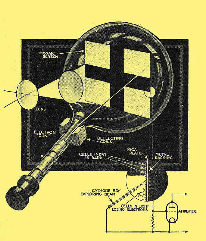
The screen of the Emitron camera is a mosaic of independent photo-electric particles, each of which has a minute capacity to the metal backing plate. The exploring cathode-ray beam forms part of a closed circuit, and in restoring the electrons lost by those cells, under the influence of light a current pulse is generated in the grid circuit of the amplifier. Click here for an iconoscope camera tube - similar to the Emitron.
The screen upon which the image found by the camera lens falls is covered by a mosaic layer of minute particles of actively photo-electric material. The formation of this layer, which is deposited on a mica plate, is a triumph of technical skill, for each particle is insulated from its neighbours and acts as an independent photo-electric cell. The mica is backed by a metal plate, which forms a common capacitor electrode to all the particles in the mosaic.
When light falls on a group of the particles in the mosaic they lose negative electricity by giving off electrons and gradually acquire a positive charge with respect to the back plate. When the electron beam passes over this particular spot in the course of its scanning travels it neutralises the charge on the cells, and in so doing causes a sudden current pulse to pass to the back plate, which is connected to the grid of an amplifying valve mounted inside the camera head. Elements of the mosaic in dark parts of the picture do not change their charge through the loss of the electrons, and so do not cause the charging current when the beam passes over them. It will be appreciated that the passage of the beam over the screen obliterates the electrical picture at each frame, and prepares it for a rearrangement of charges if there has been any movement in the subject since the last frame was transmitted.
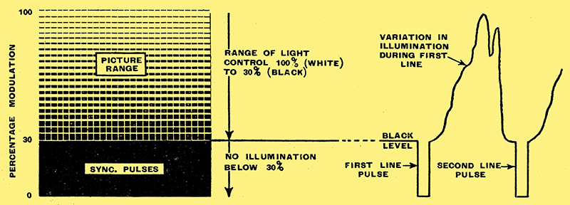
Graphical representation of the allocation of the available modulation of 100 per cent. between the picture and synchronising signals.
We said earlier in this article that the electron beams in the Emitron camera and in the cathode-ray tube at the receiving end follow the same course in tracing out the picture. They do not do this of their own accord, but must be locked together by synchronising signals. Pulses for this purpose are sent by the transmitter to the camera as well as to the receiving station at the end of each line and again at the bottom of each frame. Circuits are included in the receiving circuit to separate line and frame sync pulses and to prevent mutual interaction between the picture and the synchronising processes. To facilitate separation of these two functions the first 30% of the possible 100% modulation of the carrier wave can be varied without producing any effect on the television screen, and sync pulses are transmitted by reducing the modulation from 30% - the black level on the picture - to zero for a period equal to 0.1 of the duration of a line, The frame sync pulse extends over about ten lines and the line pulse is kept going within this period.
Action of the Time Bases
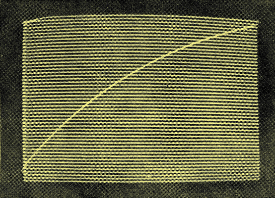
Actual photograph of the path of the light spot in a. television tube. The line spacing has been increased for clarity. The frame fly-back is visible because the time base is not under the control of the transmitter. Actually it starts in the bottom right-hand corner, but a line flyback has carried it to the left while it has travelled vertically four or five lines.
In the time bases the growth of the charge on the capacitor, if allowed to continue indefinitely, would in due course cause the anode of the gas-filled triode to which it is connected to flash over and empty the capacitor, reducing its voltage to the initial value. The valve can be made to discharge before this saturation point is reached by applying a positive voltage to the grid. This is supplied by the sync pulse, which is thus able to trigger the time base exactly at the right moment.
No attempt is made to keep, the, sync pulses off the control grid of the cathode-ray tube, since they serve the very useful purpose of keeping the grid below the 'black' level during the fly-back period. This is chiefly of advantage in the case of the frame fly-back which can be plainly seen in the raster, or faint network of lines produced-by the uncontrolled time bases when the station has closed down.
It would require a long series of articles to do justice to the wealth of ingenuity which has gone to the perfecting of detail both in transmitters and receivers, but the foregoing covers most of the essentials of the system as a whole.
The cathode-ray beams in the Emitron camera and the cathode-ray tube at the receiver follow parallel courses in analysing and tracing out the picture. In practice the beams themselves are not visible.
|