|
Single-ended Radio-frequency Pentodes
The new valves all have the same external appearance and are of the metal type.
From their beginning screened tetrodes and pentodes have been of the double-ended type; that is, the anode or grid has been brought out to a connection at one end of the valve and the other electrodes to pins at the other end. The object of this has always been to keep grid and anode connections as far apart as possible in order to keep the grid-anode capacity at a minimum.
Departures from this practice are now being made both in Germany [1] The Wireless World, November 10, 1938 and in America, and screened valves are now made with all connections brought out to the base pins.
Such single-ended types designed for ordinary receiver applications are now available in America under the type designations of 6SJ7 and 6JSK7. In effect, these are single-ended forms of the common 6J7 and 6K7 pentodes. They differ from the Telefunken single-ended valves [★] See Extras menu - Footless Valves largely because the elements of the Telefunken tubes are placed horizontally, while those of RCA are vertical as usual. The relative advantages of the two arrangements as to ease of manufacture and strength are controversial, but it is clear that they lead toward different placing of the lead-in wires.The Telefunken arrangement almost automatically produces two groups of wires which may conveniently be shielded from each other by a transverse metal partition.
The RCA valves have a different scheme of shielding, with no attempt to divide the space into compartments. The terminal pins are evenly spaced about the usual circle, with the input-grid pin diametrically opposite to the anode pin in order to minimise capacity between the two. This alone is insufficient, and it is necessary to reduce these capacities both inside the valve and in the base and socket.
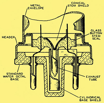
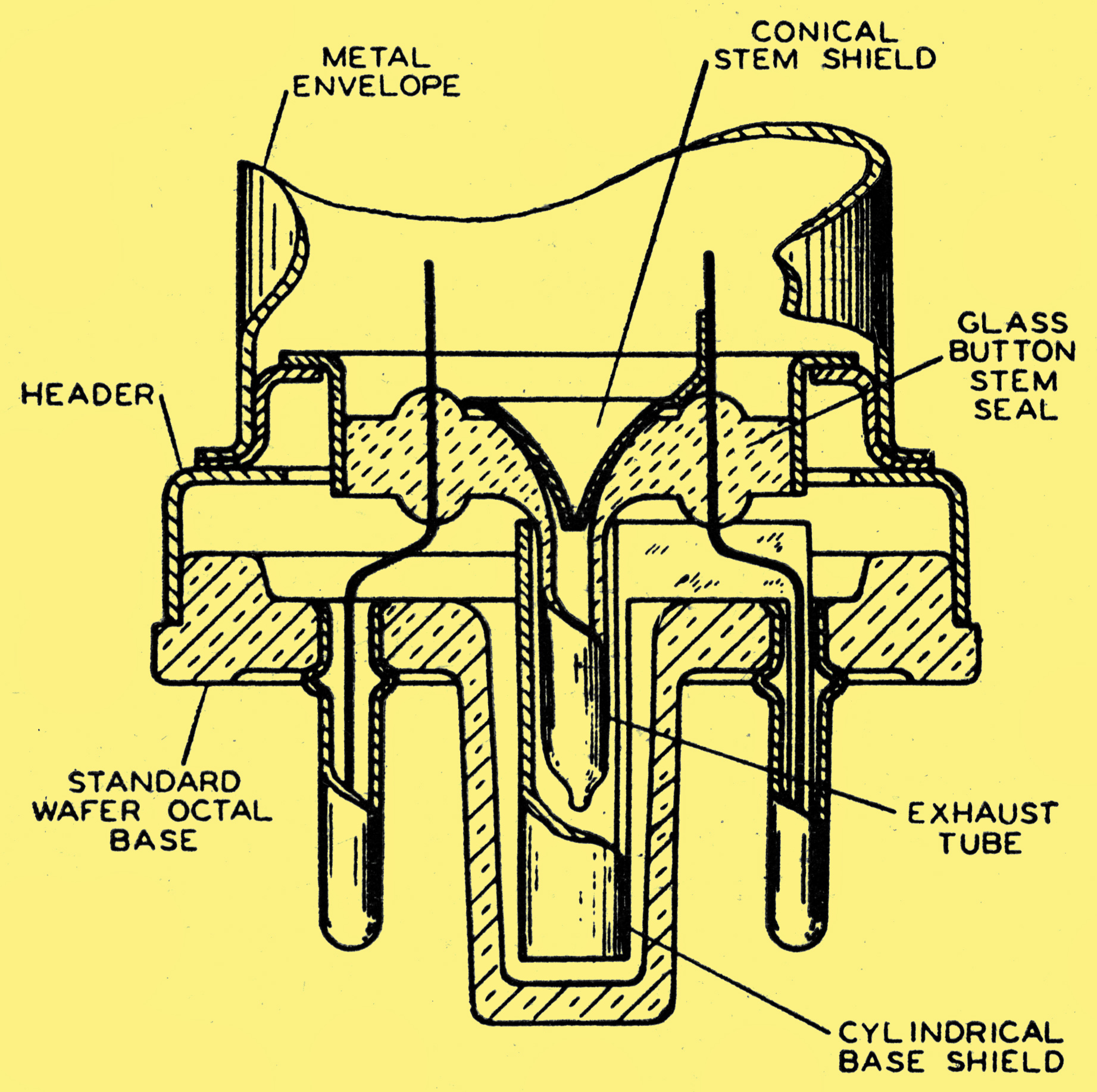
Fig. 1. - This drawing, reproduced by courtesy of RCA, shows the internal screening arrangements of the new American valves.
Reference to the cross-sectional drawing of Fig. 1 will make clear the method of capacity reduction. The grid-anode capacity in the base and socket is reduced by the cylindrical base shield, which acts as a screen between grid and anode leads and base pins. This shield is connected to the metal shell, and is contained,within the central spigot. This somewhat unconvincing device does what is desired. In a typical American 'wafer' socket the capacity between diametrically opposite terminals is about 0.005 pF, but when a 6SJ7 or 6SK7 valve is inserted this drops to the negligible value of 0.0001 pF. In another type of socket the capacity was 0.01 pF for the empty socket, dropping to 0.003 pF upon inserting the valve. Nearly the same effect is obtained by the use of a metallic locating pin instead of the hollow insulating pin containing the tubular base shield, but the capacities to frame are slightly higher.
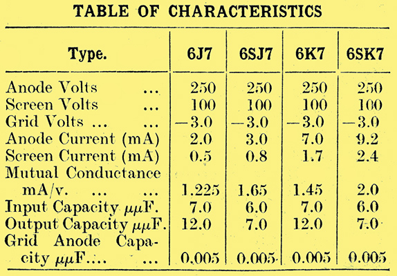
Figures for these valves and for their double-ended counterparts are given in the table, and it is clear that the former are the better, providing undesired effects do not result in the associated circuits when they are all placed below the baseplate. That this possibility is not too serious has been shown by published discussions which may be summarised as follows: In using top-grid bottom-anode valves such as the 6K7 it is usual to mount all valves above the baseplate, hence it becomes necessary, after all, to bring each anode or grid lead through the base plate in order to make possible a coupling to the next stage. This partially spoils the base-plate as a shield and introduces leads too long for good ultra-high-frequency amplification. Even at ordinary high frequencies the tuning may be disturbed by accidental displacement of the flexible lead to the top cap, especially where such a movement may introduce or alter regeneration.
It is, therefore, reasonable to abandon the baseplate altogether as an inter-valve shield, retaining it merely as a mechanical foundation and an electrical return-circuit for the un-tuned circuits. Viewed in this way the single-ended pentode seems attractive rather than dangerous. Mechanically, the advantage is on the same side. Valves are exchanged more easily; the leads are shorter and stiffer, and, above all, it is easier to mount or to repair the interstage coupling devices, since the associated wiring does not pass through the baseplate.
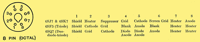
Fig. 2. - Base connections of the new valves.
The hum voltage induced into the grid circuit by the AC filament current depends partially upon the capacitive coupling of these circuits in the base of the valve. The pin arrangement chosen (Fig. 2) shields the grid pin from the heater pins.
This same form of construction has also been adopted for certain triodes, the 6SF5 or the 6SQ7, which have characteristics equivalent to the 6F5 and 6Q7.
Triodes
These triodes are commonly used in current American AF amplifiers. In the case of receivers the triode is, of course, often found in the same shell as a detector diode. In either case it has been customary to build the triode with a 6.3 Volt heater, an amplification factor of 70 to 100, and a mutual conductance about 1.2 mA/V. The effective audio-frequency input capacity of such a valve is high because it is roughly equal to:-
Ceff = Cgc + (1 + A)Cga
where
Cgc is the grid to cathode capacity
Cga is the grid to anode capacity
A is the amplification
(The effect of the load is ignored for simplicity)
The tendency is, therefore, to short-circuit high-audio frequencies. In the effort to reduce this effect it was natural to employ a top-grid connection to reduce Cgc and Cga, but the practical value of that construction is somewhat dubious. In high-fidelity audio amplifiers where high-frequency audio response is required the designer may discard the high-μ tube in favour of two stages of the more tractable moderate-μ variety. On the other hand, the designer of less costly PA equipment and of broadcast radio receivers is commonly so concerned with the reduction of hum pick-up that he provides liberal high-note shunting in the form of an input circuit enclosed in grounded metallic braid. It becomes doubtful whether the reduction of Cgc inside the tube warrants a top-grid connection. Thus, there remain only the questions whether the top grid offers lower Cga and hum pick-up. As regards hum, the RCA single-ended high-μ triode 6SF5 introduces less than is picked up by the leads to the volume control of various radio receivers. A better view is obtained by considering the permissible hum level quantitatively. The equivalent hum voltage on the grid of the single-ended 6SF5 is stated by RCA to be approximately 100 *mu;Volts across 0.5 MΩ. Whether this is acceptable depends upon the impedance of the 6SF5 input circuit and the gain of the amplifier; In the two-stage audio systems used by radio receivers the hum output is well down. A 50 μW hum output is unobjectionable, and this level will not result for a normal 6SF5 unless the following amplifier gain is several times that of the usual loud speaker pentode and the grid impedance ahead of the 6SF5 is several times that normal to radio receivers. Hum outputs below 10 μW are probable.
As regards the capacities, Cga is 2 pF for the 6F5 and 2.6 pF for the 6SF5, while the input and output capacities show a considerable reduction for the single-ended valve.
Some of the foregoing, especially the illustrative material, is from copyrighted engineering information of the RCA. It is used here by permission of RCA Manufacturing Co, Inc.
|