|
4-valve 5-Watt Ultra-Linear Amplifier
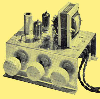
The completed amplifier.
Introduction
The General Electric Co Ltd have been responsible for many high fidelity audio frequency amplifiers within the past few years. Two of the amplifiers designed in their laboratories, the 'Williamson' and the '912', are claimed to have been built in greater numbers than any similar type. Even in the USA several firms market the 'Williamson' as a factory assembled product.
Both these amplifiers have an output exceeding ten Watts and a fidelity rating considerably better than the associated apparatus, i.e. the loudspeaker and the record player, it is, therefore, unlikely that any improvement in amplifier design would be justified at the present stage, though higher-powered 'Williamsons' (50 Watt) are sometimes used when a greater output is required.
It is felt, however, that many people do not require either the high power output or the exceptional fidelity and range of tone control provided by the above amplifiers and, for use with lower-priced loudspeakers, etc. (which represent excellent value for money), an amplifier having a lower initial cost is called for. This amplifier is now presented for the home constructor as the 'Junior'.
Circuit Design
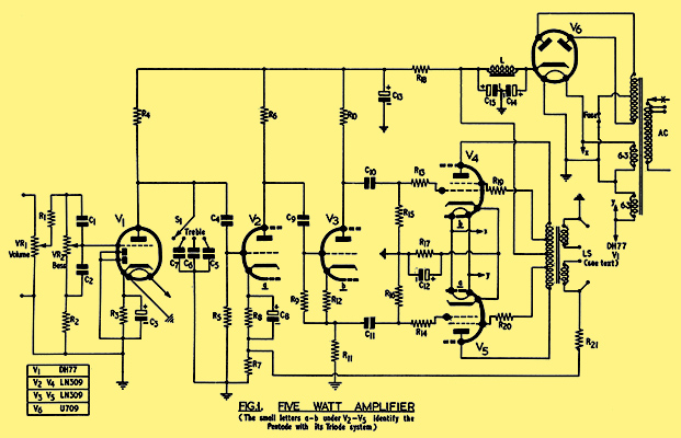
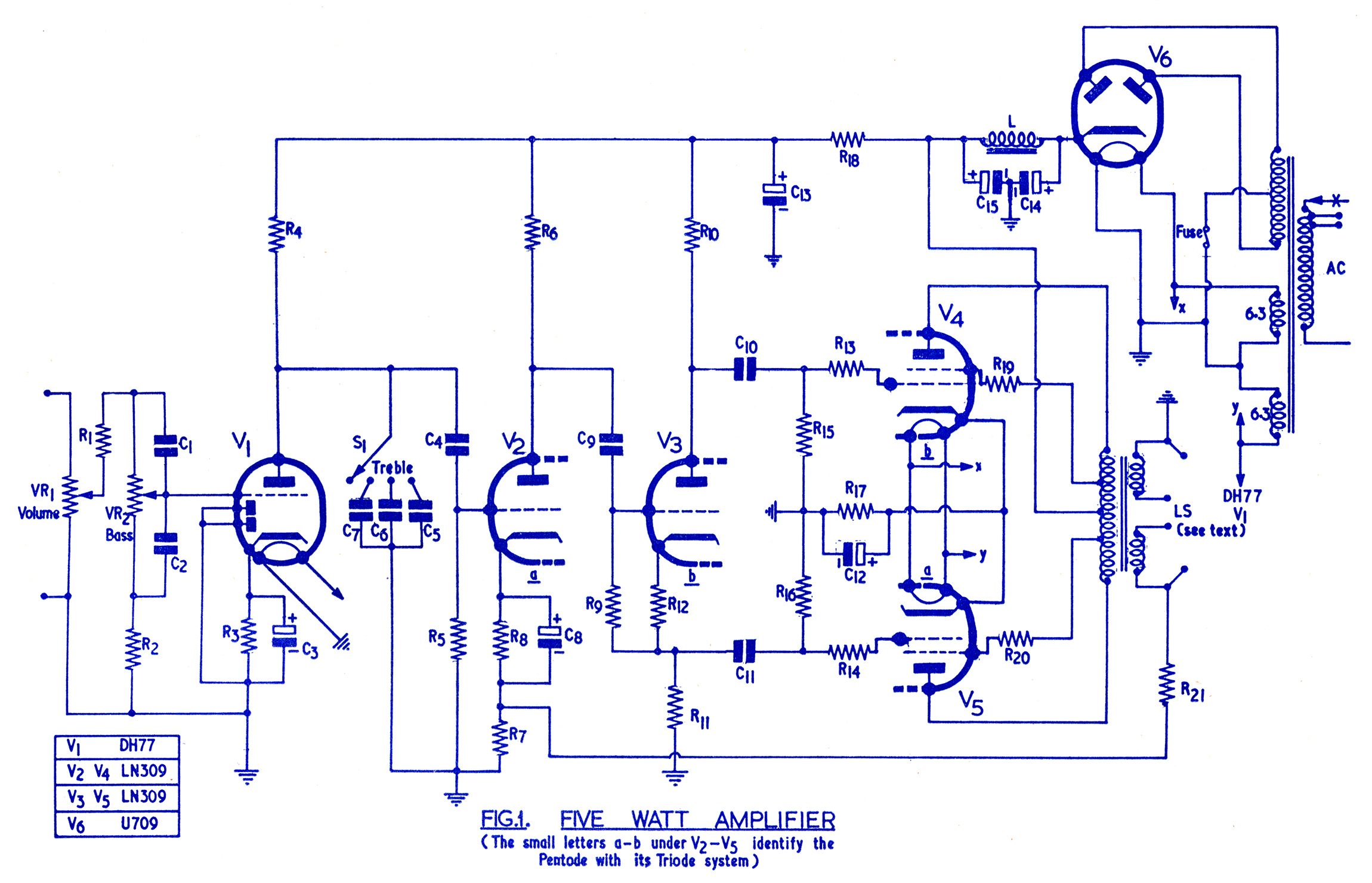
Fig. 1 Five Watt Amplifier.
The small letters a-b under V2-V5 identify the pentode with its triode system.
Valve line-up: DH77, LN309, LN309 & U709.
The 'Junior' amplifier has an output of five Watts with less than two per cent distortion, with an anode supply voltage as low as 250 Volts so that the smoothing capacitors and mains transformer are low priced. Four valves are used, two of which are triode-pentodes connected in the ultra-linear (UL) circuit, giving five stages of amplification with only three valves, the fourth (U709) being the rectifier. Approximately six dB degeneration is applied from the output to the second stage. Before the first valve is a bass control to increase or decrease the lower frequencies, and between the first and second valves a stepped treble control giving four degrees of response to the higher frequencies, These controls are simpler and use fewer components than those employed in the '912', but are capable of giving satisfactory results from LP and from normal 78 records. The full range of control is also available when connection is made to an AM or FM radio receiver. The circuit is shown in Fig. 1.
The overall sensitivity with the tone controls set level is such that full output is given for half a Volt input, which is more than adequate to cater for all the medium-priced crystal pickups. Lightweight needle armature pickups may require a slight modification to the input circuit, and the makers recommendation should be followed. The basic sensitivity of the amplifier from the grid of the first valve is considerably higher, fifty millivolts (0.05 Volt) giving full output.
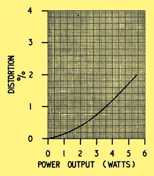
Fig. 3 15Ω secondary load with 8,000 Ω anode-to-anode primary load.
In Fig. 3 is shown the behaviour of the amplifier the distortion, which is under 2% at 5 Watts, falls below 1% at 3 Watts.
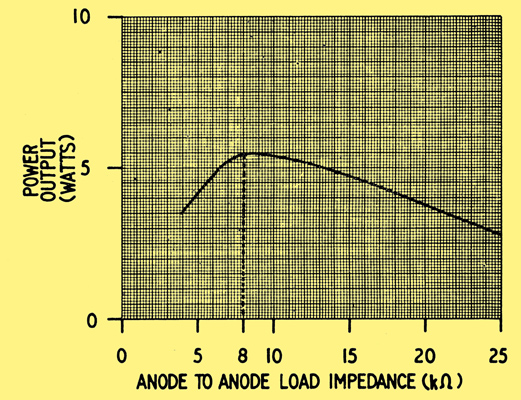
Fig. 4 Output for 2% distortion.
Fig. 4 shows that the amplifier is not critical to the output load impedance used and, although 8,000 Ohms is the optimum, a satisfactory performance is obtainable from 6,000 to 16,000 ohms or higher. This is one of the many desirable features of the UL circuit which enables the GEC Junior to out-perform other low-priced amplifiers and, without change of output transformer ratio, either one or two loudspeakers could be used with no serious increase in distortion.
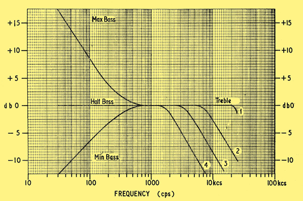
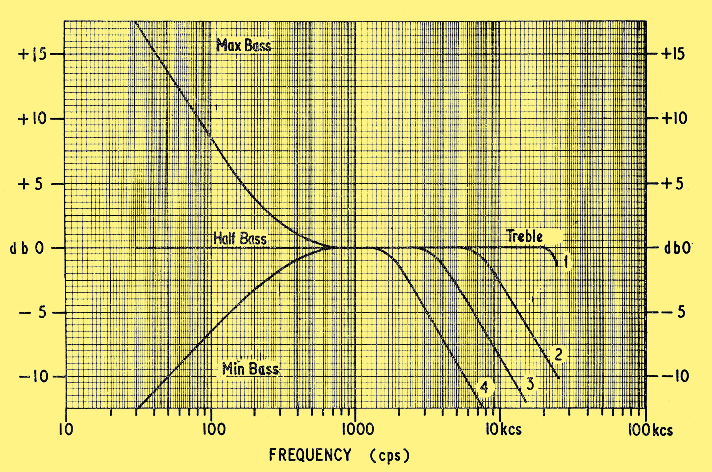
Fig. 2 Frequency response.
Fig. 2 shows the total range of frequency response available at various settings of the two tone controls, which are completely independent of each other. The bass control is so arranged that the response is level when the control knob is set half-way. When the treble control is set clockwise the response is level to 15 kHz.
The Operating Conditions for the Valves are as follows:
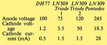
Table 1 Valve operating conditions.
The Power Supply
The Junior amplifier requires a power supply of 250 Volts at 65 mA DC, and this is provided by a U709 rectifier from a transformer having a 250-0-250V winding. Two fairly large electrolytic capacitors C14, C15 of 32 μF each are used with a choke L of 5 Henrys. The two 6.3V heater windings are connected in series so as to provide 12.6 Volts for the LN309 valves, whereas the DH77 and U709 are connected from one side of either winding and to their junction point, which is earthed, and so obtain 6.3 Volts. A fuse protects the transformer in case of a short circuit. When connecting the two 6.3 Volt windings together they must be series-aiding or the LN309 will not operate, though no damage will be done. The other two valves will, of course, heat with either connection.
Circuit Details
The output stage uses a pair of LN309 valves V4, V5 in the UL circuit with the screen grids connected to taps at 20% of primary turns. One of the triodes, V3, is used as a phase-splitting stage to provide a push-pull input for the output valves. The other triode, V2, is used as a voltage amplifier with degeneration (negative feedback) applied to its cathode. Valves V2, V5 comprise one of the triode pentodes and V3, V4 the other, this arrangement giving the neatest wiring; however, the difference is not marked and V4, V5 could be interchanged. The two resistors R10, R11 should be a matched pair, though the actual resistance is not critical. From the components list it will be seen that R18 has a similar specification so that a pair of well-matched resistors may be selected from the three if measuring gear is available. It usually is possible to pick a pair matched to within 1,000 Ohms, but satisfactory operation is given if this matching cannot be done./p>
Negative feedback (degeneration) is applied via R21 to R7. The value of R21 will depend on the loudspeaker impedance used; with a 15 Ohm speaker the resistance will be 330 Ohms and half this value, 150 Ohms, with a 3.5 Ohm speaker. However, very satisfactory results are obtainable with a compromise value of 220 Ohms, giving a slight fall in sensitivity with a 15 Ohm speaker and an equivalent slight increase in distortion with a 3.5 Ohm speaker. The difference is inaudible and only apparent on measurement.
The bass control VR2 should be wired so that C2 is connected from the tapered end of the resistor to the slider. This is the anti-clockwise end looking from the spindle. The operation will not be so smooth if the opposite connection is used. The bass control is connected between the volume control VR1 and the first valve, V1.
Mechanical Details
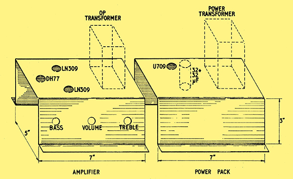
Fig. 5 Chassis layout.
A combined chassis may be used if preferred.
The amplifier has been made up on two small similar sized chassis so that, if required, the power supply may be placed at the bottom of a cabinet and the amplifier in the most convenient position for use. However, there is no objection to the use of a combined chassis provided that the input of the amplifier is kept away from the power transformer.
The two chassis Fig. 5 are of identical size for ease of manufacture and their dimensions are 7in x 5in x 3in. The point-to-point wiring is shown in Figs. 6 and 7.
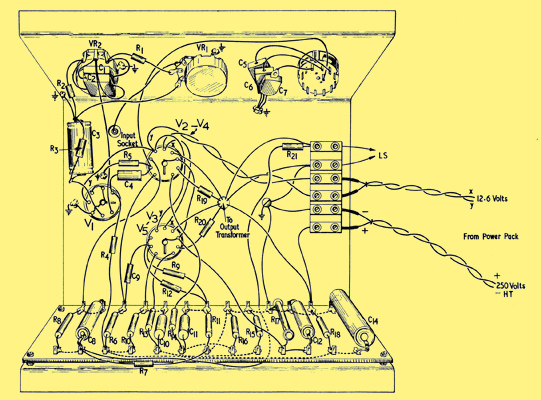
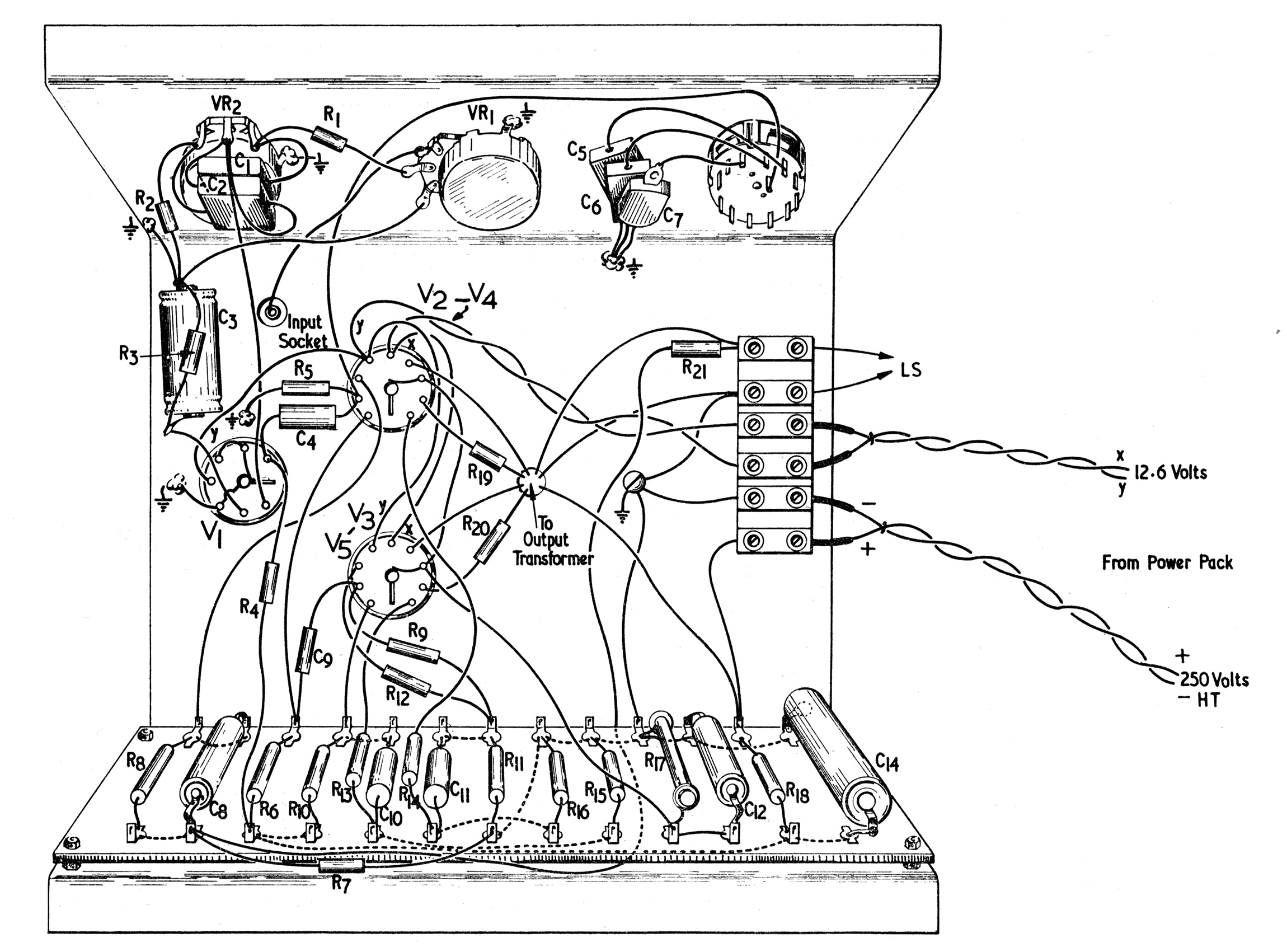
Fig. 6 Point-to-point wiring diagram of the amplifier.
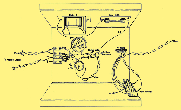
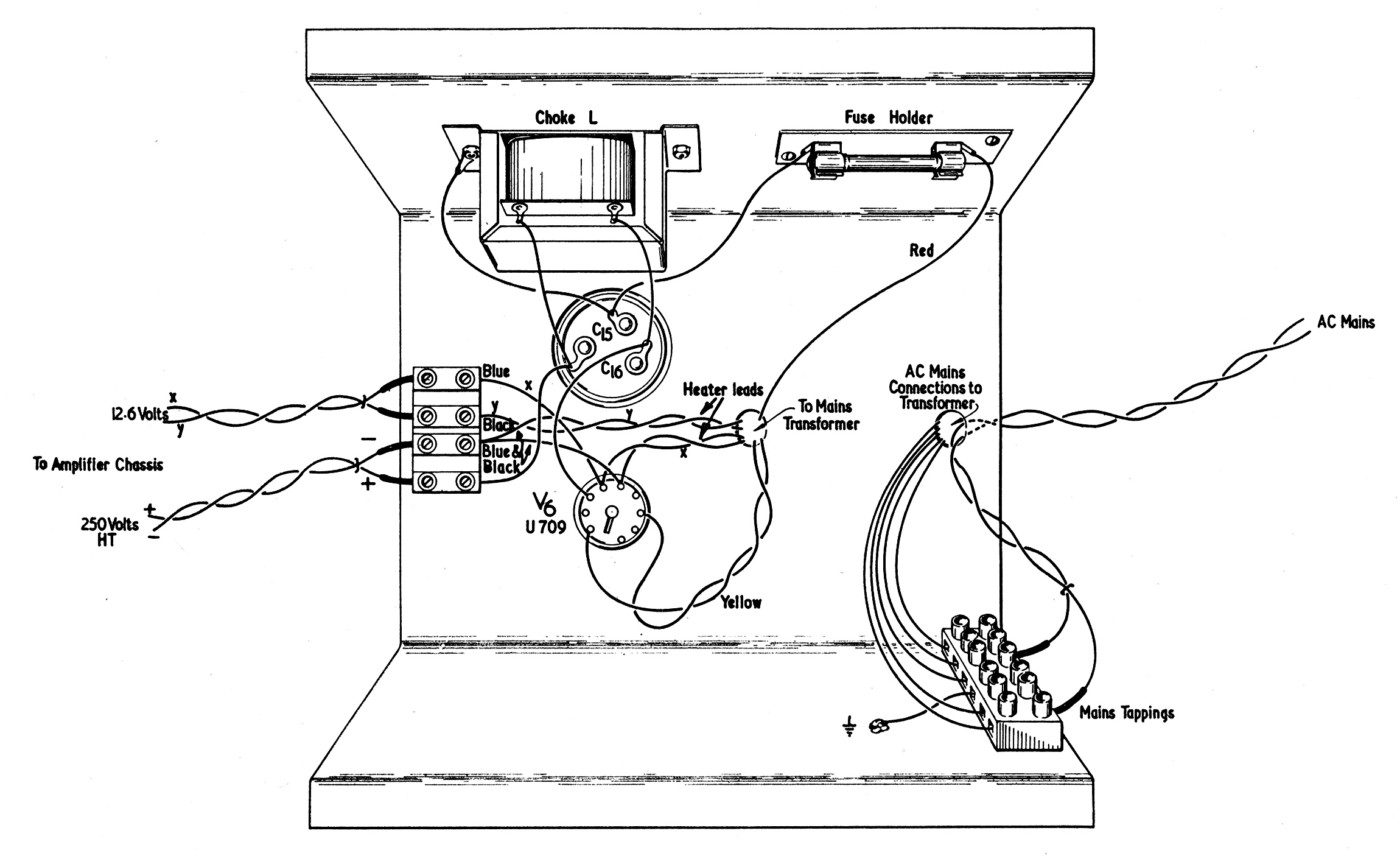
Fig. 7 Point-to-point wiring diagram of the power pack.
Fig. 7, the power supply, is straight-forward and no difficulty should be experienced in its assembly. A suitable mains tapping strip is fixed to one of the vertical chassis walls and the connections from the transformer primary taken to it; some transformers have four primary connections, 1)0 2)200/216 3)220/230 4)240/250 and others have five, 1)10 2)0 3)200/210 4)220/230 5)240/250. The additional ten volt tapping enables a more accurate voltage setting to be made. The transformer actually used in the amplifier was of this type, but this feature is not essential, and the more usual four connection type is equally suitable. A fuse of 500 mA rating is connected between the transformer secondary centre tap and chassis to protect the rectifier and the transformer in case of excessive current. A point worth mentioning here applies to those constructors who wish to use a transformer which they already own but which has a higher secondary voltage than 250-0-250. A resistance may be connected in series with the fuse to reduce the DC voltage, a 300 ohm 3 Watt rating being suitable if a 300-0-300 Volt transformer is on hand.
Although a duel-section capacitor C15, C11, is shown, two separate ones are suitable. The choke is not critical, adequate space being available for a larger one should it be handy.
The amplifier chassis comprises more components, but the assembly is assisted by a tag board containing most of the resistors and capacitors. This should be made up before being mounted on the chassis as some of the wiring, shown in broken lines, is done at the back for neatness, but this is not essential and it could be done on top of the tag-board.
The three controls are mounted on the opposite side to the tag-board. This form of assembly leaves plenty of room on the chassis deck and makes it easy to check the wiring.
A six-way connector is fixed at the end of the chassis remote from the first valve, and to this are connected the 250 Volt supply, the 12.6 Volt heater supply and the two loud-speaker connections. The output transformer is provided by the makers with four connections, and the instructions provided with it should be followed to cater for either 15 or 3 to 4 Ohm speakers. The resistor R21 should not be connected until the amplifier is known to be working properly. This resistor controls the feedback, but if it is wrongly connected the distortion will be increased. Once the amplifier is operating properly, and it is known that no wrong connections have been made, R21 may be connected whilst listening to some music. If the volume decreases the resistor R21 is connected correctly. If, however, the volume increases the connections to the secondary of the transformer should be reversed.
The Output Transformer
The output transformer is provided with two secondary windings which may be connected in series or in parallel to cater for 15 or 3.5 Ohm loudspeakers. The appropriate ratios are 24 : 1 and 48 : 1, but other ratios could be chosen, e.g. if two 3.5 Ohm speakers are to be used the ratios should be made 32 : 1 and 64 : 1 which would give a satisfactory match with the 64 : 1 ratio to either one or two speakers. A series connection would provide 32 : 1 giving an equivalent anode-to-anode load of 15,300 Ohms with one 15 Ohm speaker. A reference to Fig. 4 will show that only a slight fall in output will result due to the use of a high load impedance.
Note
In the circuit diagram, the treble control is shown inserted between the anode of V1 and chassis. In the point to point wiring diagram, the control is shown connected between the grid of V2 and chassis. The latter is to be preferred since it will remove, or reduce, clicks when operating the control.
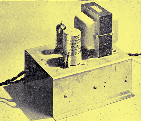
Above-chassis layout of power supply.
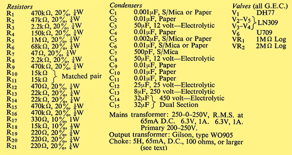
Table 2 Components List.
C6 should have been given as 0.001μF
|