|
The majority of valve manufacturers publish their valve data in a form which is understandable to engineers, but may not be entirely clear to the home constructor. It is hoped therefore that the following notes may be of some assistance in interpreting such data.
In general the data may be divided into the following main headings: limiting values, characteristics and operating conditions, it being important to distinguish between these three subdivisions.
Limiting Values
These values must not be exceeded. For normal receiving types, the values given are design centre ratings. This means that an allowance is made, in the data, for normal variations of mains voltage and component tolerances, so that if a valve has a maximum anode voltage of 250 V for instance, it can be used in a design where the working anode voltage is 250 V when the mains supply is at its nominal value. A temporary increase of 5% in the mains voltage may cause the anode voltage to rise above 250 V, but the valve manufacturer has already allowed for such variations in determining the ratings, this not harming the valve in any way.
Some special purpose and industrial valves are rated not on design centre, but absolute ratings. This means that the maximum values quoted must never be exceeded, whether due to mains fluctuation or other causes, and the equipment designer must make due allowances for these. Where a valve is rated on the 'absolute' system, this will be stated in the data.
For a pentode valve, the limiting values given will probably include the maximum anode voltage (Va max.), the maximum screen-grid voltage (Vg2 max.), the maximum dissipations of these two electrodes (pa and pg2 max.) and the maximum cathode current (Ik max.). It may be found that at the maximum anode and screen-grid voltages, the maximum cathode current cannot be attained, the limit being the dissipation. The 'working area' of such a valve is illustrated in Fig. 1, which shows that voltage, current and power ratings are all important.
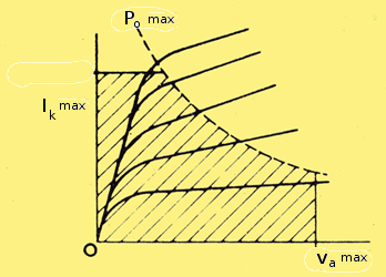
Fig. 1. Voltage, current and power limitations.
The Va(b) maximum is sometimes quoted in valve data. This is the maximum voltage which can appear on the anode when the valve is not passing current, and must not be confused with Va maximum, this being the maximum voltage which can appear at the anode during normal operation.
If a pentode is to be triode connected, it will be realised that the maximum voltage which can be applied to the 'anode' will be limited by either the maximum screen or maximum anode voltage, whichever is the lower. It must not be assumed that the maximum dissipation is pa max + pg2 max. This will depend on the ratio of anode to screen current, and which of these electrodes first reaches its maximum dissipation.
The Vh-k maximum is often quoted in the limiting values, particularly in the case of valves for series operation where the heater-to-cathode voltage is likely to be quite high.
Very often, particularly in the case of power output valves, a maximum value for the grid resistor (Rg1-k maximum) is given under fixed bias and self bias conditions. This is a very real limit although the reason may not be immediately obvious. In power valves, the grid becomes heated due to its proximity to the cathode, tending to emit electrons. This leaves the grid with a slightly positive charge and it therefore attracts electrons from the cathode. Providing Rg1-k is not too large, this state of affairs will reach equilibrium, but if Rg1-k is large, the charge on the grid becomes accumulative, the cathode current rises, the anode dissipation rises, the grid emission increases, and this state of affairs can lead to the destruction of the valve.
Characteristics
The characteristics quoted in the manufacturers data are normally measured under static conditions. In the case of RF pentodes and output pentodes these correspond fairly closely to the operating conditions, the main difference being that whereas characteristics are usually measured with fixed bias, the operating conditions refer to operation with cathode bias, unless otherwise stated.
For voltage amplifying triodes and pentodes, however, there is a wide difference between the two. The characteristics are given with fixed anode (and screen-grid) voltages, whilst in normal use a resistance is used in the anode setting a limit to the anode current which will flow.
For many of the older type triodes, the characteristics are given at Va = 100 V, Vg1 0V. It may even be found that under these conditions either the maximum cathode current or maximum anode dissipation is exceeded, This indicates that the characteristics cannot be measured under DC conditions, but only under pulsed conditions.
Line output valves, which are normally biased well back, also have their characteristics quoted under pulsed conditions, and this is also true of the triode sections of some frequency changers.
The three main parameters, gm, μ and ra are probably already well known to constructors. For triodes, all three are normally quoted, but if only two are given the third can be calculated from μ = gm x ra where:
μ is the amplification factor
gm is the mutual conductance (in mA/V)
ra is the anode impedance (in kΩ).
For RF pentodes, gm is the most important of these parameters, since the gain of a stage having a tuned circuit with an impedance Z as load, is given by: Gain = gm x Z.
The ra is also important, this effectively being in parallel with the load and, unless it is fairly high compared with Z, will reduce the stage gain.
It is not usual to quote μ for a pentode, since it is rarely used; the value is exceedingly high, being several thousand. The parameter μg1-g2 is often quoted for pentodes. This is known as the inner-mu or amplification factor between the control-grid and screen-grid. It has several practical uses, and can be regarded as the μ of the valve when triode connected.
The most useful parameter for a voltage amplifying triode is μ since this gives some indication of the voltage gain which can be obtained from the valve.
Since the voltage gain is given by: Gain ≈ (μ Ra) / (ra + Ra) (where ra is the anode impedance of the valve, and Ra is the load) the gain can never in fact reach μ, but if for example Ra is made equal to 3 x ra, the gain will equal 75% of μ.
For frequency changers the important parameter is gc, the conversion conductance. This is rather similar to gm in the case of a pentode, being the relation between a change in grid voltage and the consequent change in anode current. In this case, however, it is not a DC measurement, and is carried out with the oscillator section working. A known voltage is applied to the signal grid at one frequency, and the corresponding anode current variation - at the intermediate frequency (i.e. difference between signal and oscillator frequencies) is measured. Thus the value of gc given corresponds to the operating conditions. The characteristics of the triode section may be given either under static conditions (Vg1 = 0) or under working conditions, in which case gm (effective) is given and the value of Rg1-k and Ig1 quoted. The bias due to the grid current is equal to Vg1 = Ig1 x Rg1-k.
Operating Conditions
As already mentioned, the operating conditions for frequency changers, RF pentodes and output valves in Class A will correspond with the characteristics. In the case of output valves, however, a few additional figures are required. These include Ra (the optimum load, not to be confused with ra), the power output which can be obtained (Pout), the drive required to give this output (Vin (RMS), and the total harmonic distortion (Dtot).
The distortion sets a limit to the amount of power which can be obtained from the valve, and it is usual to limit the distortion to 10%.
If the input voltage required for full output is not given, it can be easily calculated, since Pout = (Vin (RMS) x gm)2 x RL.
Hence Vin (RMS) = (1 / gm) x (Pout / RL)0.5.
With cathode bias, the value of gm is slightly lower than that obtained with fixed bias, and allowance should be made for this factor when calculating Vin. For push-pull operation, the bias can be obtained either by a common cathode bias resistor or separate resistors for each valve. The data will usually state which method is used but if in doubt, a quick check can be made by multiplying the total cathode current (under no-signal conditions) by the cathode bias resistor, thereby calculating the bias voltage. Valves in push-pull are usually biased back slightly from the Class A operating point, and operated under Class AB conditions. Some text-books recommend that for push-pull working the anode-to-anode load should be twice that for a single valve, although in practice this is rarely found to be the case. The reason is that with single valve operation, the load is chosen to give the maximum output with 10% total distortion. This distortion is made up of 2nd, 3rd and higher order harmonics.
When two valves are used in push-pull, the even harmonics cancel, therefore with twice the normal load, twice the output is obtained with less than 10% distortion. By biasing the valve back slightly and reducing the load, more than twice the output can be obtained for 10% distortion, and there is also a reduction in the standing anode current of the two valves.
For Class B output stages cathode bias cannot be used, and the fixed grid voltage required is given. It is quite usual for the grids of Class B stages to be driven positive during operation. Since the valve will take grid current under these conditions the impedance of the driver stage must be kept low or distortion will result. If the peak value of the input voltage (= 1.4 x V in(RMS)) exceeds the bias voltage, the grid will go positive. With both Class AB and Class B output stages, the anode current increases with the output power. This is indicated in the data by Ia (0) (no-signal current) and Ia (max. sig.). When considering rectifier requirements, the latter figure must be used.
RF Pentodes
In addition to the information given under characteristics, several other figures may be quoted. The grid voltage for a 100:1 reduction in gm may be given. This indicates that the valve has a variable-μ characteristic.
Rin and Req are sometimes given, particularly in the case of valves intended for use at VHF. Req the equivalent noise resistance, is a measure of the noise introduced by the valve. It is given as a resistance since the noise from a resistance is a constant value, depending on the value of the resistance (temperature and bandwidth assumed constant). If a valve has an Req of 1kΩ, it means that a resistor of 1kΩ connected between grid and cathode would produce as much noise as the valve itself.
The input impedance Rin is usually several times larger than Req. At low frequencies, the input impedance of a valve is very high, but at frequencies of the order of 30 MHz it begins to fall. This is due to the transit time of electrons between grid and cathode. Rin is usually quoted at 50 MHz. The value at any other frequency can be calculated from:
Rin (f ) = Rin (0) x (f 0 / f )
Where Rin (0) is the input impedance at frequency f 0 and Rin (f ) is the input impedance at frequency f. Thus if Rin = 4kΩ at 50 MHz it will fall to 250Ω) at 200 MHz.
Inter-electrode Capacitances
The capacitances between various electrodes are often given on data sheets. These are important when the valve is used at RF. The three most common capacitances quoted are cin cout, and ca-g.
The input capacitance, cin is the capacitance between the grid and all other electrodes except the output (i.e. the anode). If a tuned circuit is used in the grid circuit of a valve, cin will be in parallel with it and will contribute to the total capacitance in the circuit.
The output capacitance, cout, is measured between the anode (output electrode) and all other electrodes except the grid, it having a similar effect on a tuned circuit connected in the anode. When a valve is used as a video amplifier with a resistive load (Ra), the combination of Ra and cout will form a top-cut circuit. (See Fig. 2.)
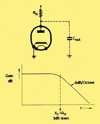
Fig. 2. Effect of cout on frequency response.
The gain of the stage will fall by 3dB (to 70.7% of its value) when Xcout = Ra. Thus the value of Ra must be kept low if the frequency response is to be maintained up to 3 MHz. Since the gain = gm Ra, gm must be as large as possible.
These requirements have resulted in the derivation of a 'figure of merit' for wide band amplifying pentodes which is given by gm / (cin + cout).
This is a useful factor when comparing different pentodes for their relative merit as wide-band amplifiers.
The capacitance between the output and input, ca-g, can be used to calculate the amount of feedback, providing sufficient information is known about the input and output circuits.
Voltage Amplifying Stages
Tables showing the values of Ra, Rk and stage gain, together with the appropriate electrode currents are normally given in the manufacturers data sheets. The current taken by such stages is usually very low - only 1 or 2mA. It is also normal to quote the grid resistor of the following valve in these tables, since this reduces the effective value of the load. This should therefore be large compared with the load - if possible, at least five times as large. There will, of course, be a maximum value for the grid resistor of the next valve, as explained above.
Operating conditions are sometimes quoted for grid current biasing. In this case no cathode bias resistor is required, but a large grid resistor (10MΩ) is employed.
Rectifiers
The two most important ratings for rectifiers, the maximum RMS input voltage (Va (RMS) max.), and the maximum output current (Iout max.) are fairly self explanatory.
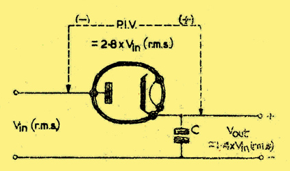
Fig. 3. Rectifier ratings.
The maximum peak inverse voltage may not be quite so clear. If an input voltage of 200V RMS is applied to the anode of a half-wave rectifier and a capacitor is connected from the cathode to earth, the rectifier will conduct on positive half cycles, the capacitor charging up to the peak value of the input voltage, in this case 1.4 x 200 = 280V. The cathode potential will therefore be + 280V with respect to earth. This condition is illustrated in Fig. 3.
On negative half cycles the anode will reach 280V with respect to earth, and the total peak inverse voltage across the valve will be 2 x 280 = 560V or 2.8 x Vin (RMS). This is the worst possible case: in practice the load on the circuit will prevent the capacitor from attaining its full charge, and in the case of a choke input filter the PIV. will be much lower (approx. 2.4 x Vin (RMS)).
The peak anode current of a rectifier may at first seem irrelevant, but a consideration of how the rectifier operates, however, will show that the rectifier does not in fact pass a steady current, but a series of pulses - one pulse every time the anode goes more positive than the cathode.
When the circuit is first connected, the reservoir capacitor must charge up, the charging current passing through the rectifier. The current will be limited by the resistance of the circuit, and the time for which it flows by the CR time constant. It is for this reason that a maximum value of reservoir capacitor is given (Cmax.) and also a minimum value for the limiting resistor to be used with this capacitor (Rlim min.).
Incidentally, strapping the anodes of a full wave rectifier valve and using it as a half wave rectifier does not double its mean current rating as some constructors might hope!
Base and Connections
There are various methods of showing base connections. Some manufacturers prefer to tabulate them, whilst others give a sketch of the valve base with the abbreviations for the electrodes written in. The most common of these are:
- ic - internally connected - do not connect to this pin
- a - anode
- f - filament (directly heated valves)
- h - heater (indirectly heated valves)
- k - cathode
- g1 - control grid
- g2 - screen grid
- g3 - suppressor grid
- bp - beam forming plates
- s - shield
- tc - top cap
- sc - side cap
- m - metallising
- t - target (tuning indicators aka magic eyes)
- x - horizontal deflection plates in cathode ray tubes
- y - vertical deflection plates in cathode ray tubes
connect pdf-ef86
In a museum exhibit, an open book symbol leads to a table of symbols, and the PDF logo leads to a data-sheet. The base type leads to a description of the base and the electrode system leads to a description of that type of valve. Examples are B9A and pentode
The same system a1, a2 etc. is used in cathode ray tubes having more than one anode.
When more than one electrode structure is included in one envelope, such as in the case of a triode-pentode, the electrodes are distinguished by the subscript letters t and p. These are only used where confusion is likely to arise: in a triode-pentode a(t) is the triode anode, and a(p) the pentode anode. The triode grid is g1(t), but the various grids of the pentode are denoted by g1, g2, g3, without a p since these obviously cannot refer to the triode.
Other subscripts which are sometimes used in this way include:
- d - diode
- h - heptode
- hx - hexode
- o - octode
- n - nonode
- q - tetrode
Valves which have two similar electrode structures in the same envelope (e.g. double triodes) use a system of 'primes' to distinguish between section. a′, g1′, k′, make up one triode whilst the other consists of a″, g1″, k″. In the valve museum where on-screen images can be small the single prime is represented by (1) and the double prime by (2) - ed.
In the old days, when the British 4 and 5 pin bases were in vogue, it was usual for all the pins to be occupied. The introduction of multi-electrode valves brought in its train, side terminals, top caps, the British 7-pin base and the British 9-pin base, before an attempt was made to standardise and use the octal base.
With rectifiers and some other types, there were, of course, more pins than required and the unwanted pins could either be left blank or omitted from the base. The abbreviation NP is used to denote no pin whilst NC is used when the pin is present but not connected to an electrode.
With the introduction of miniature valves of the A construction using 'all-glass' bases, the problem of electrode supports came into the picture. With the old 'pinch' type valves, the anode was supported by two rods mounted in the glass pinch. An electrical connection was taken out from one of these. The miniature valves do not use a pinch, and supporting rods can only be connected down to the base pins. It is sometimes necessary to provide an additional support for the electrode structure. This support may not make good electrical contact with any electrode, and the pin to which it is connected should therefore not be used for electrical connections. The pin will be marked 'ic' on the base diagram and must be left blank.
Most small valves can be mounted in any position, although it is as well to consult the valve data to ensure that there is no restriction. In the case of power valves having a high gm, horizontal mounting is only permissible if the major axis of the grid is kept vertical. This is because the grids of power valves run quite hot and are liable to sag. If the grid to cathode spacing is small - as it is in order to obtain a high gm - there would be a danger of the grid touching the cathode if the major axis was horizontal. (See Fig. 4.)
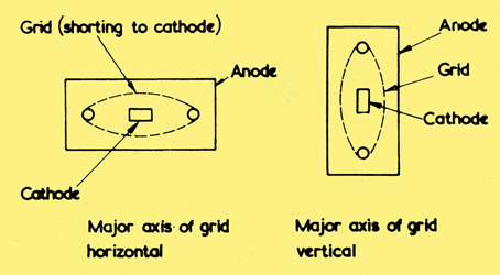
Fig. 4 (left). Major axis of grid horizontal, and (right) major axis of grid vertical.
See also Use of Valves
|