|
What is 'Good Practice'
The recently issued War Emergency, British Standard BS1106 sets out a code of good practice in respect of the use of radio valves; by due regard to its provisions optimum operating conditions and good valve life can be ensured. This article, which is a survey of some of the basic theoretical considerations which form the justification for the Code of Practice, explains the reasons for the recommendations made in the Code.
Only a small part of the Code of Practice deals with the more general and perhaps more obvious aspects of valve use. The major part is devoted to information and advice on specific points, much of which appears not to be generally known or for which the reasons are imperfectly understood.
Valve Ratings
The manufacturers' published data includes a number of 'Ratings' which must be considered as limiting values. It must not be assumed that any one of them may be exceeded because others are not approached. To take as an example a rectifier, the ratings would normally include the maximum input voltage and the maximum DC output current. The use of an input voltage lower than the rated maximum cannot justify a DC output current higher than the rated maximum.
A radio valve is a complicated structure, the design of which must always be a compromise between a number of physical, mechanical and chemical considerations. For instance, the design features which determine the input voltage rating of a rectifier are not the same as those which determine the output current rating. The permissible maximum current may be limited by anode dissipation or by cathode emission or both, whilst the permissible maximum input voltage may be limited by inter-electrode spacing, as well as by the anode dissipation. Evidently then, the different ratings of the valve are interdependent to some degree, but certainly not inter-changeable in any simple manner.
Many valves include among their ratings the maximum frequency of operation. A variety of different factors may call for this rating, such as the eddy-current heating of the valve electrodes and connections, the dielectric loss heating of the glass seal through which the electrode connections pass, the loss of valve efficiency due to transit time (i.e., the time taken by an electron to travel from the cathode to the anode), or, in the case of a mercury vapour rectifier, the time necessary for the ionised vapour to deionise. It will be evident that it may be possible in some cases to raise the frequency of operation above the rated maximum if other ratings of the valve are appropriately reduced, whereas in other cases the frequency limit will be an absolute limit which may not be exceeded in any circumstances. Accordingly, the advice of the manufacturer should always be taken when contemplating the use of a valve at a frequency in excess of the rating.
Heater Voltages and Currents
The Code of Practice stipulates that in general the heater voltage should not vary more than 7 per cent. each way from the rated value and that in some cases the regulation must be even closer. Moreover, emphasis is laid on the lesser-known requirement that 'low heater voltages are as much to be avoided as high voltages .... '
In a valve the emitted electrons collect round the cathode to form a space charge. This space charge acts as a kind of reservoir from which the electrons constituting the space current of the valve are drawn. In practice the valve will be designed so that the space current (which is made up of the anode current and the screen currents if any) will be far below the total possible cathode emission.
The cathode emission, however, is a high-order function of the cathode temperature, which in its turn is a function of the heater voltage. Thus a comparatively small drop in the voltage gives rise to a considerable drop in the cathode emission.
If the valve is, for example, an output valve, the total cathode emission under the reduced temperature conditions may be insufficient to maintain the anode current, and in this event the grid voltage/anode current characteristic will not be linear and distortion will result. In the case of a rectifier, the consequences of too low a voltage are somewhat different but no less serious. Here the decrease of emission will give rise to an increased voltage drop across the valve and this will raise the power dissipated in the valve. The point is considered at greater length later in this article, but it can be said that one consequence of this increased dissipation may be the release of residual gas from the electrodes, and this in turn will result in a still further decrease in emission. Thus a vicious circle is established which will ultimately destroy the valve or its associated equipment. Even if the normal anode current of the valve is fairly small and the total emission is adequate to maintain the anode current, the operation of the cathode at too low a temperature is still undesirable, for another reason.
It should be appreciated that the condition of the cathode coating is largely determined by the processing which takes place in manufacture and that this processing is designed to distribute the active element through the thickness of the coating and in its surface. The maintenance of the emission during the useful life of the valve is dependent upon the surface of the coating being continually replenished by active material migrating to the surface. This migration is dependent upon temperature, and the operation of the cathode at too low a temperature may result in its rapid deactivation and the consequent shortening of the valve life.
On the other hand, it should not be supposed that the main risk arising from the use of too high a voltage is that the heater may burn out. If the cathode is operated at an unnecessarily high temperature, excessive evaporation (sublimation) of the emissive coating will take place. Not only does this shorten the life of the cathode coating but it results in excessive deposition of the active material upon the grid and other electrodes. Some of the undesirable consequences of such deposition are considered more fully later in this article, particularly in relation to grid emission.
A further point which is often overlooked is the undesirability of connecting valve heaters in series, unless they have been specially designed for this purpose, as, for example, in the case of AC/DC valves. Normally the manufacturer's data will make clear whether a valve is designed for constant voltage or constant current operation, but in cases of doubt it is wise to make specific enquiries of the manufacturer if series operation is desired. If several valves designed for constant voltage operation are connected in series (thus giving the same value of current through all the heaters), and if one should have a resistance slightly greater than the others, the power dissipated in that one heater will be greater. The heater material has a large positive resistance/temperature coefficient, and thus the resistance and hence the temperature, of the heater which is already running hotter than the others, will rise further still. In this way a small percentage change in the supply voltage can result in a considerably larger percentage change in the voltage across one of the heaters which are connected in series across the supply.
Mounting
The Code of Practice recommends very strongly that valves should be mounted vertically with the base downwards. It is a not uncommon practice to squeeze valves into odd corners by mounting them out of the vertical, and it is also true that in many cases no apparent harm results. In the case of mercury vapour rectifiers, no exception to the recommendation for vertical mounting is admissible since it is essential that liquid mercury should be prevented from collecting on the electrodes or on the upper portions of the bulb. Even with other valve types mounting out of the vertical is not to be recommended; partly on the grounds of heat distribution, partly because of the risk of electrodes becoming displaced and so causing changes of characteristics, and partly because of the possibility of the valve being more susceptible to vibration and so causing microphonic noise.
Amongst receiving valves, rectifiers or output valves run rather hot and an unequal distribution of the total heat may easily result in part of the valve structure reaching an excessive temperature. One common consequence of running a valve in an inverted position is that the increase in temperature loosens the base.
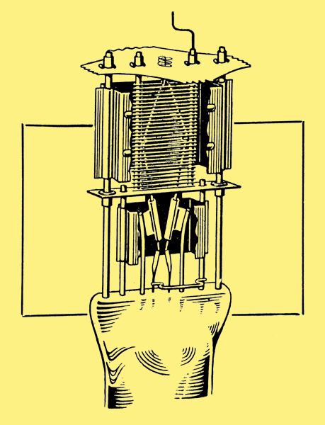
Part section of a valve employing flat grid structure.
Directly-heated valves with their relatively long and thin filaments are likely to be rather more troublesome so far as electrode sagging is concerned than are indirectly-heated valves where the cathode is of more rigid construction. Valves having a flat grid structure rather than a circular structure may also be more prone to this trouble if the valve is not vertical.
In both these cases the difficulty can be minimised by mounting the valve in such a way that the plane of the filament or grid is vertical even if the valve itself is not vertical. In the case of valves in mobile or portable equipment the arrangement should be such that the valves are vertical when the apparatus is in its usual operating position.
Heater - Cathode Insulation
Indirectly-heated valves with automatic bias or in cathode-follower or phase splitting circuits provide some examples of applications calling for an appreciable potential difference between the cathode and the heater. BS1106 deprecates the use of standard indirectly-heated valves in circuits where this potential difference exceeds 100 Volts.
The cathode assembly of an indirectly-heated valve consists of a small metal tube on the outside of which is sprayed the emissive coating and inside which the heater wire is inserted. The insulation between the heater and the metal tube is normally effected by spraying the heater with an alumina cement before insertion. It is a relatively thin coating and undue liberties should not be taken with it. In valves specially designed for operation under conditions where a high potential difference is to be maintained between the heater and the cathode, additional precautions are taken during manufacture both in regard to the insulating material and its subsequent processing.
The insulation resistance between the heater and the cathode is dependent upon the cathode temperature and also upon the potential difference and the sense or polarity of this potential. The capacity between the heater and the cathode, too, is a somewhat erratic quantity since the heater is liable to move within the cathode under the influence of temperature changes. For these reasons the heater-cathode impedance should not be included in radio-frequency circuits where high stability is required. It is worth bearing in mind that one of the consequences of a potential difference between the cathode and the heater may be the attraction of electrons from the cathode coating to the heater. Since the heater normally has an alternating potential applied to it any electron, current between heater and cathode may be modulated by this potential and so cause the introduction of hum. It is preferable, therefore, that any potential difference should maintain the heater negative with respect to the cathode, but it should be appreciated that it is similarly undesirable for the heater to be appreciably negative with respect to the grid.
Electrode Temperatures and Gas Release
With the exception of mercury vapour rectifiers and a few other special valve types the majority of radio valves are 'hard', i.e., the bulb contains the minimum of gas. If gas enters the bulb or is freed from within the bulb, the valve is said to have gone 'soft' and the effect on the valve's characteristics will be very great indeed. These effects arise from the gas molecules being broken up as the result of collisions between them and the electrons flowing in the normal way from the cathode to the anode. The gas is then said to be ionised and there will be present ions carrying positive or negative charges. Many of the positive ions move to the cathode, and under the influence of the potential existing between the anode and the cathode their velocity when they arrive at the cathode may be sufficient to cause considerable damage by the bombardment of the emissive surface. Apart from this point the mere presence of positive ions in the vicinity of the cathode has the effect of partially neutralising the space charge and the effect of this will be to increase the anode current which, as we shall see, may result in the release of further quantities of gas.
It is very exceptional for gas to be able to enter a 'hard' valve as a result of any sort of leakage, but the valve electrodes and the electrode supports are metallic and will contain a certain amount of occluded gas which may be driven from 'solution' by an excessive increase of temperature. This point is taken care of in fixing the valve ratings, and several of the recommendations in the Code of Practice are also based upon it. For instance, the Code emphasises the need to avoid the use of valves ' . . . as oscillators or under any other circuit conditions which result in appreciable grid current unless such a requirement is covered by the specification .... ' The grid current referred to here is, of course, the so-called 'grid positive current' formed by a flow of electrons from the cathode to the grid when the instantaneous grid potential is allowed to become positive, or insufficiently negative, with respect to the cathode. This grid current necessarily dissipates power at the grid and the, consequent rise in temperature of the grid may result in gas release. Moreover, apart from the temperature rise, the bombardment of the grid by the arriving electrons may also contribute to the release of occluded gas from the grid surface.
Control of Screen Voltage
The avoidance of gas release is also one of the explanations of another interesting recommendation in BS1106, which is probably very far from generally known. The recommendation in question reads: 'It is desirable that the resistances used in the supply network for voltages on screen grids of multi-electrode valves should be kept as low as possible. Aligned grid valves operating with the screen voltage substantially lower than the anode voltage should derive the screen supply from a potentiometer network. Unaligned grid valves, other than frequency changers, may derive the supply by means of a series resistance.'
Small manufacturing variations in the positioning of the electrodes in aligned grid valves result in rather wide variations of screen current from one valve to another. Thus the replacement of a valve in a circuit where the screen supply was derived through a series resistance rather than from a potentiometer might cause the screen voltage to depart greatly from the designed value. This would cause a marked change in performance and the rise in anode current might result in raising the anode temperature to a value at which appreciable gas release takes place. Unaligned grid valves employing a suppressor grid are not normally so critical in this respect.
Grid Primary Emission
In any simple consideration of the operation of a radio valve, it is assumed that the cathode is the sole source of the electron stream. Ideally, the control grid of a valve when operated under Class A conditions would neither collect nor lose electrons, and the input resistance of the valve would be infinity. In practice these simple conditions do not hold exactly and the valve electrodes other than the cathode can and do emit electrons which produce irregularities in the operation of the valve.
Grid primary emission is a thermionic emission occurring in exactly the same way as, but fortunately to a much lesser degree than, the thermionic emission from the cathode. It will be appreciated that the valve grids, and more particularly the first or control grid, are heated by thermal radiation from the cathode and that this effect is increased by reflection and radiation from the surfaces of the other electrodes. The resultant grid temperature under certain conditions may be sufficient for appreciable electron emission to take place.
Since grid primary emission is thermionic in character, its prevention or reduction is evidently in part a question of grid cooling. The valve will have been designed in such a manner that, under the conditions permitted by the ratings, the grid or grids will operate at a temperature at which grid primary emission is not troublesome. The cooling of the grid is effected partly by conduction through the grid supports and partly by radiation from the grid or from special cooling fins which may be provided.
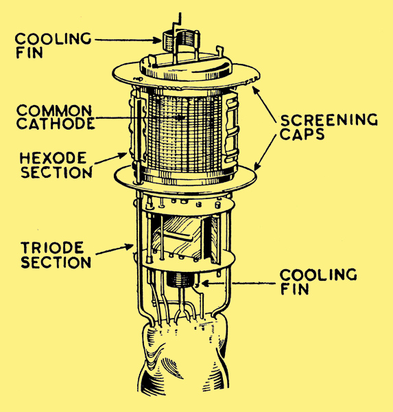
Illustrating the use of grid cooling fins in a representative triode-hexode frequency changer.
The efforts of the valve designer will be defeated if a valve is used under conditions where more heat is dissipated on the grid than has been allowed for in design, and this adds further weight to those clauses of the Code of Practice which are concerned with the avoidance of the use of valves under conditions where electrode temperatures may rise unduly.
It was mentioned, earlier in this article, that an excessive cathode temperature could result in the evaporation (sublimation) of the emissive coating of the cathode and its deposition upon the other electrodes of the valve. If a grid becomes contaminated the possibility of primary emission is very greatly increased since the contaminated surface has a greater thermionic emissivity than the original clean metallic surface.
The electrons so emitted will tend to pass to an electrode carrying a more positive potential. In general, this electrode will be the anode, but in any event the stream of electrons leaving the grid will constitute a current which, under the normally accepted convention, flows from the grid to earth through the external path. Such grid current is called 'grid negative current' to distinguish it from the 'grid positive current' which flows from earth to the grid through the external path whenever the grid potential permits the collection of electrons from the cathode stream.
This flow of grid negative current may set a limit to the resistance which may be connected between the grid concerned and the cathode, since the flow of grid negative current through the external resistance gives rise to a voltage drop which, in the case of a control grid, would offset the bias potential by a value proportional to the external grid resistance. This point explains the necessity for keeping such external resistance as low as possible.
Although it does not occur as a result of grid primary emission, it is necessary to consider here the case of grid negative current arising from another cause, and generally referred to as 'gas current'. It has been mentioned already that a small residual quantity of gas may be present in the bulb and further gas is liable to be released by an increase in temperature of the valve electrodes. Collision between the electrons from the cathode and gas molecules results in ionisation of some of the latter, which become positively charged and will travel to the grid and other negatively charged surfaces. The arrival of positively charged ions at the grid can be regarded as constituting a grid negative current comparable with the loss of electrons from the grid. It has already been pointed out that the flow of grid negative current offsets the bias potential on the valve to an extent determined by the external resistance of the grid circuit. The reduction of bias voltage increases the anode current and this will raise the temperature of the anode. A vicious circle may therefore be established in which the flow of gas current in the grid circuit causes an increase in temperature of the anode and so results in the release of more gas and consequently in an increase in the gas current itself. This danger of the valve 'running away' is obviously dependent upon the external grid resistance and may be avoided by ensuring that this resistance is as small as possible.
These considerations requiring a low external resistance apply equally to all valve grids, but the Code of Practice is more specific in the case of the first or control grid and quotes recommended maxima which should not be exceeded. For voltage amplifying valves, the figures are 1 MΩ when automatic bias is used and 0.5 MΩ with fixed bias, but in the case of output valves having an anode dissipation of 10 Watts or over, these limiting resistances are still further reduced to 0.5 MΩ when automatic bias is used and 0.1 MΩ with fixed bias. Output valves generally run rather hotter and have a larger grid surface, and for these reasons grid emission is likely to be greater and the external resistance must be correspondingly reduced.
The distinction which is made between the permissible external grid resistances with automatic bias and with fixed bias arises from the fact that, as mentioned already, the flow of gas current offsets the bias potential and, in turn, may bring about a still further increase in gas current. If, however, automatic bias is used, the increase of anode current arising from the offsetting of the bias voltage will cause a compensatory increase of bias voltage. Because of this the conditions are more stable than when fixed bias is used, and the employment of larger values of grid resistance is justified.
It is necessary to consider a further effect which may occur when a valve is used under conditions where grid positive current is flowing. For example, grid positive current will flow to the control grid of a valve operating under 'positive drive Class B' conditions or, momentarily due to overload in the case of a valve which is nominally working under Class A conditions. The flow of electrons to the grid in such cases as have been mentioned may result in electrons being released by impact from the grid material. This form of grid emission, arising from electron bombardment, is known as grid secondary emission and will result in the grid losing electrons, probably to the anode. Thus the flow of electrons from the grid, by secondary emission, offsets the arrival of electrons to the grid from the cathode. This phenomenon is illustrated below.
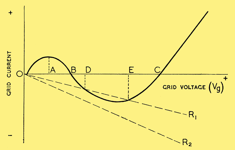
Current/voltage characteristic of a grid in a valve containing another electrode at a positive potential.
Starting at a point in the neighbourhood of Vg=0, the grid current is zero. If the grid is made more positive, electrons are attracted to it, thus constituting a grid positive current. This current rises to a maximum at a point shown on the diagram where Vg=A, and subsequently it begins to fall because of the increasing loss of electrons from the grid arising from the resultant grid secondary emission. As the positive grid voltage is still further increased and the bombardment of the grid becomes greater, the secondary emission increases and the grid negative current will eventually attain the same numerical value as the grid positive current which is causing it. At this point, Vg=B, the total external grid current is zero. Beyond this point the value of the grid negative current becomes numerically greater than the grid positive current, and thus the resultant grid current is negative. At a still higher value of positive grid voltage, a further effect becomes apparent when the potential gradient around the grid is such that the secondary electrons move back to the grid itself rather than to the anode. This, of course, results in a drop of the grid negative current and at the point Vg=C the total external grid current once more becomes zero. From here on, the grid current is increasingly positive.
It will be apparent from the above that there are three sets of conditions under which the external grid current can be zero and that the corresponding grid voltage can be either Vg≅0 Vg=B or Vg=C.
If the grid of a valve has no DC connection to the cathode the external grid current is evidently zero. It may be, however, that the valve is operating at the point C on its grid characteristic and that the grid, consequently, is at a large positive potential. Under these conditions a considerable electron current will be flowing to the grid and an equally considerable electron current flowing from the grid as a result of secondary emission. The condition is a stable one and the valve may remain in this state indefinitely. Obviously, since the grid potential is large and positive, the anode current of the valve will be considerably higher than the normal and the effect of this will be to increase the anode dissipation and thus damage the valve.
This is one very important reason for the insistence in the Code of Practice that ' . . . in no circumstances should valves be operated without a DC connection between each electrode and the cathode.'
Mention is also made in BS1106 of the practice of 'keying' by opening the screen circuit of a valve whilst the normal anode and grid voltages are maintained. This is another example of the operation of a valve without a DC connection between each electrode and the cathode.
The phenomenon of grid secondary emission, moreover, is of importance even if the grid has a DC connection to the cathode. Referring again to the diagram above, it will be seen that two dotted lines are included, marked R1 and R2. These are simply the current/voltage characteristics for two values of resistance, drawn on the same co-ordinates as the grid current curve. The flow of grid negative current in a valve circuit where a DC connection exists between the grid and the cathode gives rise to a voltage drop down the DC resistance of such polarity that the grid becomes positive with respect to the cathode. R1 and R2 are assumed to be two values of external grid resistance where, of course, R1 is greater than R2.
Considering first the operation of the valve with an external grid connection having a resistance R1, it will be observed that the grid current curve and the R1 characteristic intersect at the two points D and E. These two intersections are conditions of equilibrium which, once established, may be maintained without the application of any external EMF to the grid. At D the equilibrium is unstable, but if a positive potential having a value greater than E is applied to the valve grid and then removed, the grid voltage falls towards zero until the stable point of equilibrium E is reached. Thus a momentary application to the valve grid of a positive potential greater than E (as, for example, by a condition of overload) may result in the phenomenon known as 'grid-locking'.
On the other hand grid locking is impossible in the case of the same valve operating with the smaller value of external grid resistance R2 because that dotted line nowhere intersects the grid current characteristic.
This argument further emphasises the requirement that the DC connection between each electrode and the cathode should have the minimum practicable resistance. The Code of Practice in fact states '. . . the apparent advantage of an 'open-circuited' electrode, or of a high resistance path, may be defeated by the valve's secondary emission characteristics'.
Grid Rectification Biasing
The very common use of grid rectification to obtain a bias voltage, particularly in cases of valves used as oscillators or RF power amplifiers, is the subject of another precaution covered by BS1106. This type of circuit is no doubt well known and consists of a capacitor and resistance used in conjunction with a valve which is being driven into grid positive current on part of each cycle. This grid positive current produces an accumulation of electrons in the grid capacitor and the mean charge potential is adjusted to the desired value by an appropriate choice of capacitor capacity and grid-leak resistance.
In the event that the valve drive is cut off for any reason, the flow of electrons to the capacitor every cycle will cease whilst the leakage of electrons through the grid-leak resistance will continue until, finally, the potential across the capacitor will fall to zero. As the biasing potential drops the anode current will rise and may very greatly exceed the rated anode current. To avoid the damage to the valve which can arise in these circumstances the Code of Practice recommends that grid rectification biasing should never be used alone. It mentions one of the possible methods of avoiding the risk described, by recommending that some of the desired bias potential should be secured in the normal manner by a resistance in the cathode lead. Thus if the grid rectification bias fails the increasing anode current will produce an increasing cathode bias and thus can save the valve from damage. For any particular application it is very desirable that the valve manufacturer's advice should be taken as to the minimum cathode bias which will ensure a reasonable security against damage.
Miscellaneous
It will be of interest to consider briefly two lesser known miscellaneous points which are covered by the Code of Practice. The first reads: 'It is, in general, undesirable that valves should be operated in such circuit conditions that the cathode current is normally cut off'. This practice, which is often adopted in equipments which are required intermittently but at short notice, may be permissible with some valves but it should not be adopted without first taking the advice of the valve manufacturer. When a valve is operated in a normal manner the cathode emission carries with it minute quantities of impurities in the cathode coating. These impurities are deposited elsewhere in the valve and have only a negligible effect upon the useful life. On the other hand, if the cathode is maintained at operating temperature but the cathode current is cut off as, for example, by cutting off the anode voltage, these minute quantities of impurities fall back on to the cathode itself with the result that the cathode surface is slowly 'poisoned' and its emissivity decreased.
A further cause of cathode 'poisoning' may arise from the presence in the bulb of very small quantities of residual gas. Under the operating conditions the residual gas is ionised by collision as has already been discussed, whereas this will not be the case if the cathode current is cut off. It can be shown that un-ionised residual gas is less rapidly re-absorbed than when ionised and accordingly, in the absence of space current, residual gas may remain and result in cathode 'poisoning'.
The second of the two miscellaneous points referred to is concerned with contact potential.
The contact potential between any two electrodes in a valve is defined very simply in the Code of Practice as the 'voltage corresponding to start of positive current to any electrode'. Evidently, the assessment of the voltage at which a current starts to flow between two electrodes is dependent upon the sensitivity of the method used to detect the current and it is therefore usual in practice to define the contact potential as the potential at which the positive current reaches some small arbitrary value. The value of the contact potential is dependent upon the two surfaces under consideration and any variation in either of the surfaces will reduce a change of contact potential.
The question of contact potential is of importance in a number of cases, but particular mention might be made of the case of the cathode/grid potential in high-gain triodes. With these valves, where the contact potential may easily be of the same order as the bias voltage, it is obviously important that due regard should be paid to it.
The Code of Practice emphasises that 'circuits which are critical as regards control of contact potential should be avoided . . .'. This condition must be observed because, as has been stated, the contact potential is dependent in any given case upon the electrode surfaces. Contact potential therefore changes with temperature and throughout the life of the valve and cannot be regarded as a stable or constant quantity.
Mercury Vapour Rectifiers
A far smaller number of valve users is concerned with mercury vapour rectifiers than with 'hard' valves of one sort or another. Partly because of this but partly because each mercury vapour application tends to be regarded as an individual engineering problem in itself, mercury vapour rectifiers are not taken quite so much for granted as are 'hard' valves. Nevertheless BS1106 does include a short section dealing with this subject.
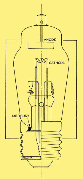
A typical mercury vapour rectifier.
The essential difference between a vacuum rectifier and a mercury vapour rectifier is that the latter contains a certain amount of mercury, partly in liquid form and partly vapour, depending upon the temperature conditions. When a potential difference is applied between the anode and the heated cathode an electron stream flows in the normal manner, and in their passage from the cathode to the anode electrons will collide with mercury vapour molecules and produce a state of ionisation. The positive ions on account of their high mass and the low potential gradient move towards the cathode at a relatively low velocity, and will neutralise the space charge existing between the cathode and the anode.
In a vacuum valve the presence of the space charge has the effect of reducing the space current and of necessitating the use of relatively high anode potentials. To remove the space charge entirely in a vacuum rectifier would require the application of very high anode voltages which might damage the valve by excessive anode dissipation and liberation of gas. The cathode, moreover, would be rapidly destroyed by the bombardment of positive ions which would be travelling at an extremely high velocity on account of the large potential between the anode and the cathode.
The introduction of mercury vapour into the valve and the consequent neutralisation of the space charge without the need for very great anode potentials permits the anode current of the mercury vapour valve to approach the total emission of the cathode, whilst avoiding the risk of cathode damage from high-velocity bombardment.
The potential difference which is necessary between the anode and the cathode in a mercury vapour rectifier in order to produce a satisfactory ionisation of the vapour is usually less than 20V. Thus, provided the anode voltage is of that order, the anode current will be unrestricted by the presence of a space charge and will only be limited by the emission available from the cathode. The principal property of the mercury vapour rectifier therefore is that it will pass a relatively large current with only a very small potential difference across it. The very low value of the rectifier's resistance and its practically constant voltage drop require the use in practice of a limiting resistance in series with the rectifier.
If it should happen that the anode voltage were applied to the rectifier, before an adequate amount of mercury had been vaporised, the flow of electrons from the cathode to the anode would result in an insufficient number of positive ions to neutralise the space charge. The internal resistance would be excessively high and the voltage drop across the rectifier would accordingly be high also. Under these conditions, the velocity of such positive ions as did exist would be sufficient to cause cathode damage by bombardment, and partly for this reason a pre-heating time is always specified in the case of mercury vapour rectifier.
By pre-heating time is meant the period during which the cathode is heated before the application of the anode voltage. Mercury vapour rectifier cathodes are normally of the high current low voltage type having a considerable thermal capacity, and an appreciable time is required for the cathode to reach its operating temperature. Subsequent to this the heated cathode will cause the evaporation of a certain amount of mercury until a new state of equilibrium exists inside the bulb. If the valve has not been recently used, or if it has been disturbed so that the mercury may have splashed on to the emissive coating of the cathode, it will be necessary to take still greater care that an adequate pre-heating time is allowed. In the latter event, for instance, the presence of liquid mercury actually on the cathode will result in very rapid evaporation and an excessive mercury vapour pressure around the cathode. If the anode voltage were applied whilst this condition persisted, arcing would take place between the electrodes and the valve would be damaged. In these exceptional cases it will generally be found that the manufacturer recommends the pre-heating time of between 15 and 30 minutes but for the routine starting of valves in regular use, the pre-heating time is less than this and may even be as short as a minute. In either case the length of the pre-heating time depends upon the size of the valve and upon the room temperature and it is safest to make sure that the recommended times for any particular type are known.
It is a common practice, and a very good practice, to make use of automatic time delay switches to take care of the necessity for a pre-heating time. These switches are generally thermal in principle and their release time, which is obviously determined by the rate of cooling of the bi-metal element, is far from negligible. It can happen, therefore, that the rectifier might be switched on again, soon after switching it off, before the delay switch has had time to return to the un-operated condition. If this should happen it is obvious that the anode voltage and the filament voltage will be applied to the rectifier simultaneously. The chance of this occurring is, no doubt, small, but it is a point well worth remembering.
The factor of temperature is always of considerable importance in the operation of mercury vapour rectifiers. The degree of ionisation of the mercury is dependent upon the pressure, and hence upon the temperature of the gas, as is also the rate of de-ionisation. If in any mercury vapour rectifier the temperature of the condensed mercury is too low, vaporisation and subsequent ionisation will be insufficient to bring about the desired condition of low voltage drop across the valve. If, on the other hand, the temperature is too high, then de-ionisation will be retarded. It will be remembered that the process of ionisation is effected by the flow of electrons from the cathode to the anode on each half-cycle when the anode is positive. with respect to the cathode, and it is, therefore, evident that ionisation is required to take place in a time short compared with the length of one half-cycle. Similarly, the vapour must de-ionise at the beginning of each succeeding half-cycle rapidly enough to ensure that de-ionisation is sufficiently complete to enable the rectifier to withstand the peak inverse voltage. If the process of de-ionisation is retarded, the internal resistance of the rectifier will be too low to withstand the peak inverse voltage and breakdown and destruction of the cathode surface will result. It is, therefore, necessary to control the operating temperatures of mercury vapour rectifiers and with large valves of this class, when normal ambient temperatures are likely to vary unduly, some form of forced air temperature control must be employed.
The published data covering mercury vapour rectifiers always specifies a limiting range of condensed mercury temperature, and due attention must be paid to this if reliable service is to be expected from the valve.
The very high current-carrying capacity of mercury vapour rectifiers, as compared with vacuum rectifiers, gives rise to the need for a special precaution in the case of the larger directly heated types. With these it may well happen that the anode current is of the same order as the filament heating current. Moreover, as has already been stated, the voltage drop across the rectifier is so low that it may be of the same order as the filament-heating voltage. If the anode and filament voltages are connected in phase or 180° out of phase, as would be the case in a normal bi-phase half-wave circuit, maximum current to the anode will coincide on each half-cycle with peak positive voltage at one or other end of the filament. This will tend to draw more emission from one end of the filament than from the other, and will also result in unequal amplitude of current in the two halves of the filament. For this reason the Code of Practice lays down that with large directly heated mercury vapour rectifiers, the anode voltage and the filament voltage should be arranged to be substantially 90° out of phase. If this is inconvenient, steps may be taken to reverse the filament terminals at regular intervals, but if this is not possible, the rectifier will usually have to be operated with reduced ratings.
See also Interpretation of Valve Data
|