|
Trigger tubes are basically similar to cold cathode diodes, but a third electrode known as a trigger or starter is employed in addition to the main anode and cathode. This trigger electrode can be used to cause the main anode-to-cathode gap to conduct, but cannot be used to reduce the flow of anode current. Thus the trigger electrode acts like the grid of a thyratron rather than the grid of a hard valve. Trigger tubes are filled with an inert gas, often neon, at a fairly low pressure.
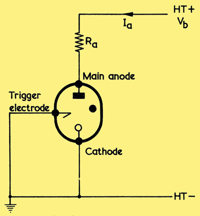
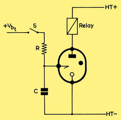
Demonstrating the cold cathode trigger tube.
A resistive load must always be used when cold cathode tubes are employed. The simple circuit above, in which the trigger electrode is earthed, will be used to explain the basic action of a cold cathode tube. As the HT potential, Vb, is gradually increased from a low value no appreciable current flows initially, and the anode voltage therefore equals the HT supply voltage. Quite suddenly, when the HT voltage reaches the striking voltage of the tube, VS, the anode-to-cathode gap conducts and the anode voltage falls to the maintaining voltage of the tube, Vm. This voltage is almost independent of the current passing through the tube. If the Ohms Law equation is applied to the anode resistor, Ra, it can be seen that the current passing through the tube, Ia, will have the value Ia = (Vb - Vm) / Ra.
Thus the current passing through any particular tube is determined by the value of the load resistor, Ra, and the supply voltage, Vb. An excessive current will damage the tube. The anode-cathode voltage must be reduced below Vm to extinguish the tube (that is, to stop the conduction). A conducting tube glows with a reddish light; this is a great help in servicing equipment which employs cold cathode tubes. Trigger tubes are often used with an HT supply voltage between Vm and Vs. The trigger electrode is normally employed as an additional anode. As the trigger voltage is increased, the trigger-to-cathode gap suddenly conducts and provides charged particles or ions which initiate conduction in the anode circuit. The trigger-cathode spacing is smaller than that between anode and cathode and therefore the trigger voltage required to initiate conduction is smaller than the striking voltage for the main anode-to-cathode gap. Some of the ions formed in the trigger-cathode discharge pass into the main anode-to-cathode gap and reduce the striking potential of this gap almost to the maintaining voltage.
Trigger Tube Cathodes
The cathodes used in trigger tubes can be divided into two main types. Oxide coated cathodes of low work function are employed in low voltage trigger tubes, but pure metal cathodes of sputtered molybdenum or nickel can be used if close tolerance tubes of high reliability are required. In both types of tube some stray ionising particles are required to initiate a discharge. If the only sources of ionising particles are stray radioactive atoms and cosmic rays, there will be a statistical delay in the striking of a tube after the necessary potentials have been applied. Some form of 'priming' is required to prevent this delay. Tubes with oxide coated cathodes are normally primed by the electrons liberated when light falls on the cathode, but a small amount of a radioactive material (such as tritium or nickel63) is included in certain types of tube designed for use in a dim light.
Visible light will not cause electrons to be emitted from a cathode of high work function and the ultra-violet light which could do so cannot pass through the glass of the tube. It is usual to employ one or two additional electrodes in this type of tube. A priming current flows to this electrode system whenever the tube is in use and provides a limited number of ions which can initiate the discharge. If too many ions are provided, the striking voltage of the tube will be lowered. The methods of priming by means of an auxiliary discharge are shown below.
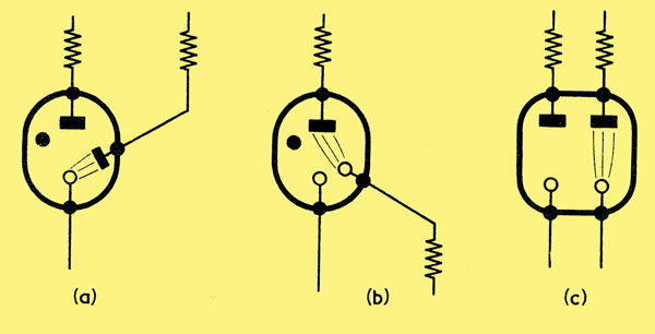
Methods of priming by means of an auxiliary discharge:
(a) with a priming anode
(b) with a priming cathode and
(c) with two priming electrodes.
A fourth method is employed in the STC G1/371K high speed tube, in which light from an auxiliary discharge passes through a mica window and primes the main section of the tube by photo-emission.
Advantages
Trigger tubes are on-off devices. That is, they are either passing a current of the value given in the equation above or they are non-conducting. There are no intermediate states of partial conduction, as in a hard valve. Thus trigger tubes cannot be used to amplify waveforms (although they can be used to amplify pulses). The ions in the gas take time to be formed and to disappear, and trigger tubes cannot therefore be used at very high frequencies. Some trigger tubes cannot be used at frequencies above about 1 kHz, whereas others can be used at up to about 100 kHz. Trigger tubes, like most cold cathode tubes, are extremely reliable components when properly used, values of the order of 0.05% failures per thousand hours being obtained. Power gains of the order of ten thousand million times and current gains of the order of ten million times can easily be obtained with ordinary trigger tubes in very simple circuits. Special electrometer trigger tubes draw currents of less than a millionth of a microamp before conduction occurs, and provide power gains as great as one million million times Such devices are extremely useful in industrial equipment. No heaters are required and no power is consumed in the anode circuit when the tube is not conducting. There is no warming up period. Trigger tubes are very cheap. Many common types are about 8s each, whilst one subminiature type can be obtained for 1s 6d.
Applications
A few of the simpler applications of trigger tubes will now be discussed. Most of the circuits employ an alternating power supply so that the trigger tube is automatically extinguished during each alternate half cycle of the mains supply voltage.
Relay Operation
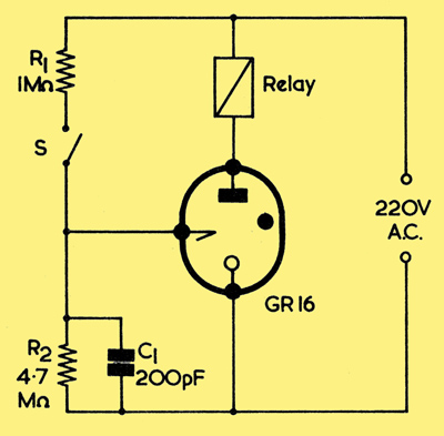
A relay control circuit.
If a pair of small contacts (such as those of a thermostat) are used to control a large current, they will quickly be damaged. Such damage can be avoided by the use of a circuit such as that shown above in which the Cerberus GR16 tube is employed. The tube will conduct during the positive half cycles of the supply voltage if and only if the contacts S are closed. The relay contacts may be designed to carry quite a large current.
If R1 and the contacts S are interchanged with R2, the relay will close when the contacts are opened.
Photosensitive Circuit
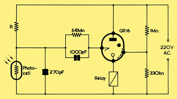
A photosensitive circuit. The photocell is a photoconductive cell such as the ORP60 or ORP61. R is about 0.5 to 2.7MΩ, depending on the photoconductive cell used.
When the light intensity falling on the photo-conductive cell C in the diagram exceeds a certain value, the relay opens? It closes again when the light intensity falls below a certain smaller value. The difference in the values at which the relay opens and closes prevents the relay from 'chattering'. The potential divider connected to the screening in the tube prevents spurious conduction. If the photo-conductive cell and R are interchanged, the relay will open at low intensities of illumination and will close as the light intensity increases.
Timing Circuits
The basic trigger tube timing circuit.
Trigger tubes are very commonly used in circuits which can provide time delays of up to about one hour. The basic circuit of such a timer is shown above. When S is closed the capacitor C charges through the high resistance R. After a time determined by the product of the values of R and C the trigger voltage will be great enough to cause the tube to conduct. The relay then closes. The time delay, t, is given by the equation:
t = RC loge(Vbt/(Vbt - Vit))
where Vbt is the trigger electrode supply voltage and Vit is the voltage at the trigger electrode when ignition occurs.
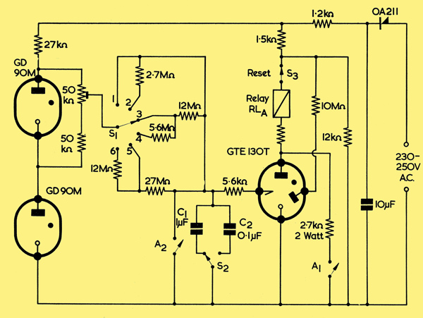
A general purpose timer. The timing capacitor, C1, must not be an electrolytic component.
A general purpose trigger tube timing circuit is shown. As shown in the Table, a wide range of delay times can be obtained by appropriate choice of the capacitor between the trigger electrode and cathode and of the resistor corresponding to R in the basic timing circuit diagram. The relay should close at a current of less than 13 mA. The total resistance of the relay and its series resistor should be 4kΩ. The Ericsson GTE130T trigger tube employs a priming anode (shown on the right hand side of the circuit symbol). The capacitor selected by S2 commences to charge when the relay contacts A2 open as the reset switch S3 is momentarily opened. The tube ignites after the preset interval and the relay contacts A1 close. The tube anode voltage is thereby lowered and the tube is extinguished, but the relay is held closed because a current passes through the contacts A1 instead of through the tube. When the relay closes, the contacts A2 short-circuit the capacitor selected by S2. (It may be advisable to insert a low-value limiting resistor (say 10Ω) in series with contacts A2 to prevent an excessive flow of current at the instant of closing.) When S3 is opened momentarily, the current in the relay falls to zero so that A1 and A2 open. The capacitor selected by S1 then commences to charge again and the tube fires at the preset interval after the operation of S3. Other contacts on the relay are used as output contacts to operate any equipment after the preset time interval.
Such a circuit has obvious uses in photographic enlarging, etc. Similar circuits have been published by other trigger tube manufacturers.
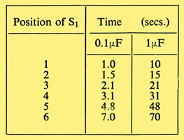
Timing periods offered in the general purpose timer.
Level Control
Trigger tube circuits are very useful for controlling the level of a liquid in a vessel. The liquid must possess some very slight conductivity.
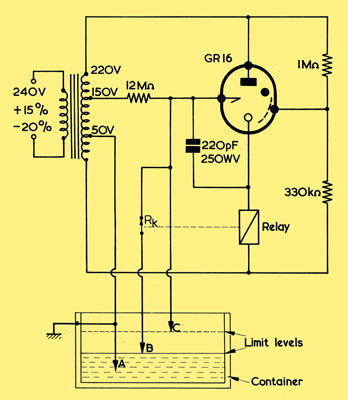
Using a trigger tube to control liquid level.
A typical circuit is shown above, when the liquid in the vessel falls below the point B, the relay closes and operates a pump which raises the liquid level. The relay contacts, Rk, open so that the pump is not switched off until the level reaches C. The difference in the levels B and C prevents the relay from operating frequently or 'chattering'. The resistance between the two electrodes immersed in the liquid should not exceed about 100kΩ in this circuit.
If the 50 and 150 Volt connections to the transformer are interchanged, the relay will open when the liquid falls below point B and close when it rises above point C.
Other Uses
Trigger tubes are much used in counting, as multi-vibrators (which may be astable, mono-stable or bi-stable), in telephone and other routing circuits, in welding timers, in electronic fence controls, in various types of protective circuits, etc. In most cases valve or transistor circuits can be designed for the same function, but trigger tubes may be preferred for reasons of cost or reliability.
|