|
Negative Feedback - Problems
We saw in the last article that negative feedback produces a smoother frequency response, reduces harmonic distortion, hum and noise introduced in the amplifier itself and stabilises amplifier performance. These improvements are obtained at the expense of gain. In valve high quality or high fidelity amplifiers, where cost limitations are less stringent than with normal domestic entertainment equipment, the loss of gain due to negative feedback represents only a minor disadvantage, and such amplifiers may have one or more relatively inexpensive voltage amplifying stages whose gain is partly or completely nullified by negative feedback.
The application of negative feedback introduces a number of amplifier design problems and we shall next examine these in this article.
Amplifier Phase Shift
In our discussion of negative feedback up to the present it has been understood that the amplifier to which the negative feedback is applied does not introduce any shift in phase of the input signal. We have assumed that the output signal always maintains the same phase relationship to the input signal at all frequencies. Under such conditions the fraction of the output signal fed back to the input terminals is always in anti-phase with the input signal, whereupon true negative feedback is provided regardless of frequency.
In practice, the circuits of an AF amplifier include a number of reactances which are given by physical capacitors and inductors and by 'stray' capacitances and inductances. These reactances will cause shifts in the phase of the input signal as it passes through the amplifier. Physical capacitive reactances are given by coupling capacitors between amplifying stages and by cathode and screen-grid bypass capacitors, whilst physical inductive reactances are given, when the speaker transformer appears inside the feedback loop, by this component and the speaker. 'Stray' capacitances are the result of inter-electrode capacitances in valves, wiring capacitances and capacitances in the speaker transformer. 'Stray' inductances appear mainly in the speaker transformer and are due to leakage inductance.
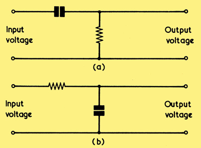
(a) If an alternating voltage is applied to this simple circuit, the phase shift between input and output voltages tends towards 90° as the alternating voltage approaches zero frequency
(b) With this circuit the phase shift tends towards 90° as the alternating voltage approaches infinite frequency
When an alternating voltage is applied to a circuit consisting of a capacitor and resistor in series, as in (a) in the above diagram (which is representative of a coupling capacitor from a voltage amplifier anode to the grid resistor of a following valve), the voltage across the resistor does not have the same phase as the voltage applied to the capacitor. At frequencies where the reactance of the capacitor is small compared with the resistance the shift in phase is low and may, in general, be ignored, but at frequencies where the reactance of the capacitor is high the phase shift is high also. If the reactance is twice the resistance the phase shift is of the order of 60°. To take an example, a 0.01nF capacitor has a reactance of about 1MΩ at 15Hz whereupon, if a 0.01μF coupling capacitor were to feed into a 470kΩ grid resistor, we could expect a phase shift of around 60° at this frequency. The phase shift, regardless of capacitor or resistor values, always tends towards 90° as the alternating voltage approaches zero frequency. The voltage across the resistor leads on the voltage applied to the capacitor.
If an alternating voltage is applied to a resistor in series with a capacitor, as in (b), the voltage across the capacitor is similarly out of phase with that applied to the resistor. At frequencies where the reactance of the capacitor is high compared with the resistor the phase shift is small but, at frequencies where the capacitive reactance is low compared with the resistor the phase shift is high. When the reactance is half the resistance the phase shift is around 60°, and it tends towards 90° as the alternating frequency approaches infinite frequency. A circuit of this type is representative of the case where there is 'stray' capacitance between a valve anode and chassis, the series resistance being given by the ra of the valve. To take a practical example, if the anode of an EF86 AF pentode (ra=2.5MΩ) fed into a 'stray' capacitance to chassis of 5pF, whose reactance is approximately 1.25MΩ at 25kHz, then we would expect a phase shift of about 60° at this frequency. In this instance, the voltage across the capacitor lags on the applied voltage.
The two examples of phase shift just quoted show that surprisingly high degrees of phase shift can occur in what appear, at first sight, to be quite innocuous amplifier circuit elements. Phase shifts are also given in series combinations of resistance and inductance, as may appear in the speaker transformer circuit of an amplifier.
It follows from what we have just noted that, if the amplifier stages enclosed within a negative feedback loop include sufficient reactive elements, it is possible at one frequency for the individual phase shifts to add up to 180°. At such a frequency the fraction of the output signal fed back to the input is then in phase with the input signal and the feedback becomes positive. If the phase shifts were predominantly due to circuits of the type shown in (a), the output signal would lead on the input signal by 180°. If they were predominantly due to circuits of the type shown in (b) the output signal would log on the input signal by 180°. Whether the output signal is leading or lagging by 180° the result will still, nevertheless, be positive feedback.
Conditions For Stability
We already know that if enough positive feedback is applied to any amplifier it becomes an oscillator. Let us now see how much positive feedback is required with an AF amplifier fitted with nominal negative feedback to make this an oscillator, too.
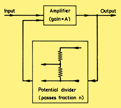
The basic negative feedback arrangement. The text discusses the requirements for stability when phase shifts exist in the amplifier
Above we have an amplifier which provides a gain of A before feedback is applied. Connected to its output is a potential divider which allows a fraction, n, of the amplifier output to be applied back to the input. This is the standard arrangement for negative feedback. The loop go in, i.e. the gain provided by any signal passing through the amplifier and then via the potential divider back to the input again, is obviously An, because it is the gain A multiplied by the fraction of the output, n, which is fed back to the input. If, at any frequency at which the phase shift in the amplifier is 180° (either leading or lagging) the product An is equal to unity (i.e. equal to one), then the amplifier will oscillate at that frequency. If the product is greater than unity, the amplifier will also oscillate, the amplitude of oscillations increasing to a level which, due to consequent changes in valve operating conditions, once more causes An to be equal to unity. Should the product An be less than unity at a frequency at which phase shift is 180° (either leading or lagging) then the amplifier will be stable and will not oscillate. Since this last condition still corresponds to positive feedback, the amplifier will show enhanced amplification at the frequency at which 180° phase shift takes place so that, whilst it is still inherently stable, it may exhibit an undesirable peak in its frequency response at that frequency.
We have seen that the simple phase-shifting circuits we have considered provide an increasing phase shift as frequency approaches zero frequency or infinite frequency. It follows that an amplifier whose overall phase shift cannot be more than 180° (lagging or leading) at either zero or infinite frequency will always be stable regardless of the value of n.
The frequency at which the product An is equal to or greater than unity at 180° phase shift does not need to be an audio frequency. In practice it will very probably appear above or below the audible range of frequencies, but the resultant oscillation will still upset amplifier operation. Where a large number of amplifying stages appear in the feedback loop, considerable care is needed to prevent 180° phase reversal at one or more frequencies. As was shown by the example of (a) in the first diagram, resistance capacitance coupling between valves provides a prevalent cause of phase shift, a shift of 60° per coupling at some low frequency representing quite a normal state of affairs. In consequence it is desirable to keep resistance capacitance couplings in the amplifier to a minimum. A good approach here is to employ direct couplings wherever possible. In the Mullard phase-splitter circuit for instance, the anode of a voltage amplifier valve connects directly to the grid of the following phase-splitter without any coupling capacitor at all. Such a circuit neatly cuts out one undesirable coupling capacitor from the feedback loop.
If the speaker transformer appears in the feedback loop (and with a high fidelity amplifier it is virtually essential that it should do so) great care has to be taken in its design to keep 'stray' capacitances, capacitive couplings and leakage inductances to a minimum. Speaker transformers intended for high fidelity amplifiers in which a high level of feedback is provided are specially designed and manufactured to meet these requirements. They are, in consequence, more expensive than the simple low-cost speaker transformers encountered in domestic entertainment equipment.
An AF amplifier without feedback will normally exhibit its highest gain over the centre of the audio frequency range, the gain dropping off to zero at frequencies below this range and at frequencies above this range. If the circuits in the amplifier are capable of allowing 180° phase shift to occur at a frequency below the AF range, or at a frequency above the AF range, but the gain A provided at such frequencies is too low to allow An to be equal to or greater than unity, then the amplifier is, as already stated, stable. Sometimes, the response of an amplifier may be deliberately reduced at a frequency well above the AF range so that the factor A is sufficiently low to ensure that An is below unity at the 180° phase shift point. This is a design technique which assumes the inevitability of 180° phase shift in the amplifier and which deliberately reduces the factor A at the frequency in question in order to retain stability.
An alternative approach where 180° phase shift is inevitable is to keep the fraction, n, of the output voltage which is fed back below the figure which allows oscillation to occur. This results in an amplifier which is stable but with reduced negative feedback at all frequencies.
Before concluding on this subject, it should be mentioned that other reactive components can also produce phase-shifts which may prove troublesome with negative feedback amplifiers. Typical amongst these are cathode bypass and screen-grid bypass capacitors. Some high fidelity designs reduce phase shifts by omitting cathode bypass capacitors from one or more of the voltage amplifiers in the loop. Apart from obviating the risk of phase shift this approach causes a reduction in gain in the amplifier before the application of feedback.
As will have been gathered from this article, the design of a negative feedback amplifier having a high performance is by no means a simple procedure. To sum up, if full advantage is to be taken of the negative feedback, there must be a high level of gain without feedback, a high level of feedback should be applied, and the speaker transformer should appear in the loop. The first two requirements mean that the initial high gain amplifier will require an output stage plus at least one voltage amplifying stage, whereupon phase shifts have to be kept to a minimum. Also, output transformer design has to be very carefully carried out to minimise phase shifts in this component.
As a final point it should be mentioned that it is possible to apply more than one feedback path to an amplifier. Some amplifiers have been produced in which additional negative feedback loops are applied to stages which appear within the main feedback loop.
|