|
Output Stages and Phase Splitters
Last time we looked at pentodes and beam tetrodes and we saw how, in the latter, the optical alignment between control grid and screen-grid wires causes the electrons emitted by the cathode to form horizontal beams which converge to give maximum electron density per beam at a plane between the screen-grid and the anode. This plane of maximum electron density is equivalent to a virtual cathode, and its existence prevents the passage of secondary electrons from the anode to the screen-grid which is characteristic of a normal tetrode. Hence, the beam tetrode has a kinkless IaVa characteristic similar to that of a pentode, and it may be similarly employed as an AF output valve.
We now turn our attention to other features of the output stage, and will also commence, this month, to deal with phase splitters.
Valve Performance
As was stated previously, pentodes and beam tetrodes offer a higher output for a given HT consumption than do comparable triodes, and they are also more sensitive. In consequence, pentodes or beam tetrodes are almost always employed in the output stages of valve AF amplifiers. Triode AF output valves are not, indeed, normally listed in valve manufacturers current lists, although the technical details given for most output pentodes and beam tetrodes specify operating conditions for such valves when triode-operated, as is given when the screen-grid and anode are strapped (i.e. connected) together.
An important feature of the performance of an AF output valve is the amount of distortion it introduces, and this can be expressed in terms of the additional harmonics of the input grid signal which are generated due to the distortion. Speaking in very general terms, triode and beam tetrode output valves operated in Class A1 (the normal mode for radio receiver output stages) cause distortion in which the second harmonic predominates. Pentodes in Class A1 produce distortion in which the third harmonic predominates. The subjective effect of third harmonic distortion is more unpleasant than an equivalent amount of second harmonic distortion, and it could be described as representing a higher degree of 'shrillness'
Because the beam tetrode provides predominantly second harmonic distortion the use of this valve in simple push-pull output stages, where second harmonics cancel out, becomes attractive. Two 6BW6 beam tetrodes are, for instance, quoted as offering 1% harmonic distortion at 12 Watts output in a push-pull output circuit. This is quite a reasonable performance for a simple output stage in which no additional distortion-reducing circuit device (i.e. negative feedback - to be discussed later) is employed. The third harmonic distortion introduced by pentodes does not cancel out in a push-pull output stage, but it is possible, by lowering the anode load impedance, to reduce the third harmonic distortion at the expense of an increased second harmonic distortion, which is then cancelled out whereupon pentode output operation in push-pull can also become attractive.
It must be emphasised that the points concerning distortion which have been given in the preceding two paragraphs are of a general nature, and apply to simple AF output circuits only. It has also to be remembered that the distortion increases with output, with the result that distortion may be small at low output settings, reaching a high figure only when the output approaches the maximum for which the valve is rated. In practice, the output stages of commercially manufactured valve radio receivers tend to employ pentode valves more frequently than beam tetrodes.
So far as home constructor designs are concerned either type of valve may be used, and it is always very desirable to employ an output transformer having a ratio which offers an anode load impedance equal to, or close to, the anode load impedance specified by the manufacturer of the valve. A widely incorrect anode load impedance may not result in a very large apparent reduction in output volume, but it can cause a significant increase in distortion.
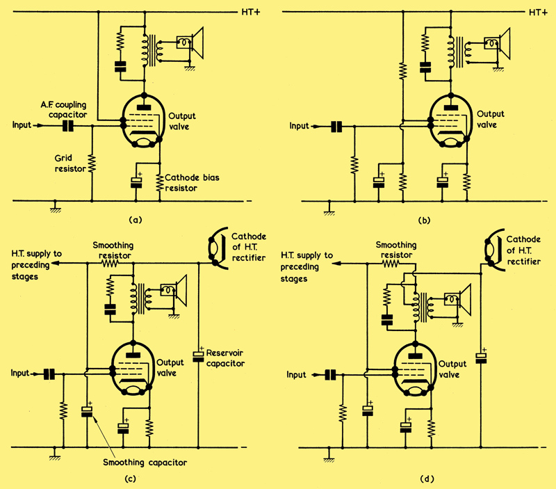
(a) ln a simple AF output stage, the screen-grid may be returned to the same HT positive point as the primary of the output transformer. A pentode is shown here, and in (b), (c) and (d), but a beam tetrode with its beam forming plates connected to cathode can be similarly employed in all cases
(b) In some output circuits the screen-grid is fed by way of a fixed potentiometer given by two resistors
(c) A typical circuit technique in which the high ra of a pentode or beam tetrode allows only a low ripple current to flow in the output transformer primary. A valve HT rectifier is assumed
(d) An improvement in the circuit of (c) which further reduces the ripple level in the output transformer secondary.
With AF output stages employing a single valve, the normal method of connection for the beam tetrode and the output pentode consists of returning the screen-grid direct to the HT positive rail, as shown in (a) above. Either type of valve may be connected up in this manner. If it is desired to operate the screen-grid at a lower potential than the anode it may be fed via a fixed potentiometer given by two resistors, as shown in (b). In general, the resistors should have values which cause about four times as much current to flow in them, on their own, as is drawn by the screen-grid, and the screen- grid should be bypassed to chassis via a capacitor of some 4μF or more. Due to the fact that the ra of an output pentode or beam tetrode has a high value (of the order of 30 to 80kΩ for either type of valve) it is possible for the output transformer primary to be returned to an un-smoothed point along the HT positive line, as in the example shown in (c). Even if there is a relatively large ripple at the point where the output transformer primary connects, the high ra presented by the valve keeps the ripple current flowing in the primary of the output transformer at a sufficiently low level to be acceptable for normal domestic applications. The circuit of (c) has the advantage that the high anode current does not flow through the smoothing resistor, where- upon this can have a high value without incurring an excessive voltage drop, and HT smoothing requirements become eased. An improved version of this arrangement is shown in (d), in which the tap in the output transformer primary is close to its upper end. The. small ripple current flowing in the lower section of the primary is approximately cancelled out, in the transformer, by the ripple current flowing in the opposite direction in the upper section, thereby ensuring an even lower ripple in the secondary.
In all the output circuits shown in (a) to (d), the output transformer primary has a resistor and a capacitor in series connected across it. This is standard practice in low-cost AF output stages employing a single valve, the function of the capacitor and resistor being to attenuate the higher audio frequencies and thereby reduce the subjective effect of the harmonics introduced by the output valve. Typical values of resistance and capacitance for an output pentode are 10kΩ and 0.05μF respectively, and it would be possible to use components offering less attenuation with a beam tetrode output valve. Circuit devices of this nature do not affect the cause of the distortion, they merely alleviate its audible effect. Alternative approaches are employed in AF amplifiers which are intended to offer a high fidelity output.
Ultra-Linear Output Stage
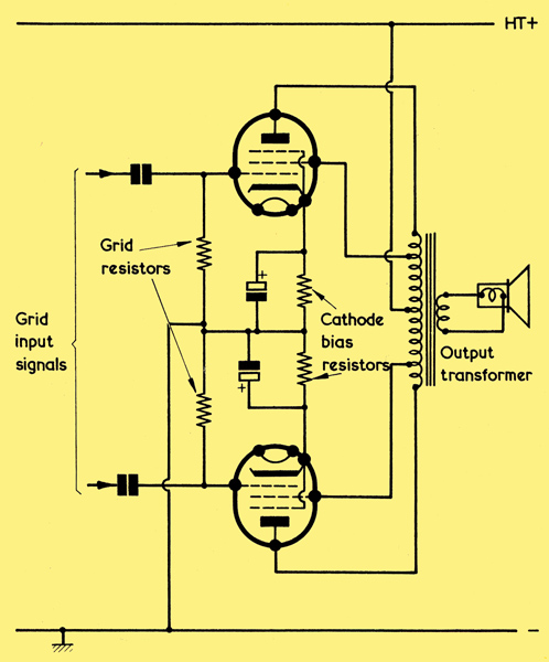
Two pentodes in an ultra-linear push-pull output circuit. This differs from a conventional push-pull pentode output circuit because the screen-grids are connected to taps in the output transformer primary.
An interesting push-pull AF output stage is illustrated above. This employs two pentodes but, whereas it is normal practice for the pentode screen grids of a push-pull output stage to be bypassed to chassis by way of a large-value capacitor, in this circuit the screen-grids are connected to taps in the primary of the push-pull output transformer, these taps being situated between the anode connections and the HT positive centre-tap. The cathode, control grid and screen-grid of each valve constitute a triode, whereupon the circuit takes up the attributes of a triode push-pull output stage as well as those of a pentode push-pull output stage. As a result, the performance of the circuit tends to fall between that of a triode output stage and that of a pentode output stage.
The distortion introduced by a pentode output stage is predominantly third harmonic whilst that introduced by a triode is predominantly second harmonic. When pentodes are employed in the ultra-linear circuit the odd harmonic distortion decreases, whereupon the remaining even harmonic distortion can be readily cancelled out in the primary of the push-pull output transformer. Thus, the circuit offers less distortion than is given with pentodes whose screen-grids are bypassed to chassis. At the same time, the available output power is somewhat lower than with two pentodes operated in the normal manner.
The circuit of shown is frequently used in the output stages of high quality and high fidelity AF amplifiers because the advantage of lower distortion outweighs the disadvantages of reduced power in such applications. The pentodes may be operated in Class A or AB1. Beam tetrodes may also be employed in an output circuit of this type.
The screen-grid taps in the output transformer primary are, according to individual output stage design, positioned some 20% to 45% of each half of the winding away from the anode end. Speaking in general terms, both distortion and power output reduce as the screen-grid taps approach the centre-tap within this range.
Valve manufacturers (notably Mullard) quote output stage operating conditions for specific screen-grid tap positions in their literature covering valves suitable for use in this type of circuit. The circuit shown is generally known as an ultra-linear output stage. In Mullard literature, however, it is referred to as an output stage operating under distributed load conditions.
Phase Splitters
When we introduced the push-pull output stage, we employed an AF transformer with a centre-tapped secondary to provide the two out-of-phase signals needed for the output control grids. The centre-tap was connected to chassis and the two outside ends of the secondary to the control grids, whereupon the input AF signal caused one grid to go positive when the other went negative and vice versa, thus providing the desired 180° phase difference between signals which is required for push-pull working.
In practical high quality AF amplifiers having push-pull output valves which operate in Class A or Class AB1, the use of a transformer to provide out-of-phase signals is not attractive because, if the transformer is not to introduce a relatively large amount of distortion, it has to be a carefully designed and expensive component. It is much simpler and cheaper to provide the out-of-phase signals with a valve or valves, and the circuits employed for this purpose are known as phase splitters. We shall next commence to consider some of the phase splitter circuits which are most commonly encountered in valve amplifiers.
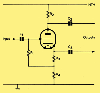
A simple phase-splitter. C1, C2 and C3 are AF coupling capacitors. R1 is the grid resistor, having a value of the order of 470KΩ to 1MΩ.
The drawing shows a very simple and effective phase splitter. In this diagram a single voltage amplifier triode is used, and equal values of resistance are connected between its anode and the HT positive line and between its cathode and chassis. The anode resistance is given by R2 and the cathode resistance by R3 and R4 in series, R3 plus R4 being equal to R2, R3 is a cathode bias resistor having a value suitable for the triode employed, grid resistor R1 being returned to its lower end. Outputs are taken, via coupling capacitors C2 and C3, from the anode and cathode. C1 is an AF coupling capacitor in series with the input signal.
Let us consider the action of the circuit when the input AF signal causes the triode grid to go positive. The consequent increase in anode current causes a higher voltage to be dropped across R2, whereupon the anode goes negative. The increased anode current has to flow through R3 and R4, whereupon the voltage dropped across these two resistors increases also. Thus, the cathode goes positive.
If the input AF signal causes the grid to go negative, anode current decreases. Less voltage is dropped across R2 and the anode goes positive. At the same time, less voltage is dropped across R3 and R4, and the cathode goes negative.
We can now see that, if an AF signal is applied to the grid of the triode a signal which is 180° out of phase with the input appears at the anode and a signal which is in phase with the input appears at the cathode. The signals at the anode and cathode are, therefore, suitable for passing on to the control grids of a push-pull output stage.
Because there is no bypass capacitor across the resistance in the cathode circuit (R3 and R4) there is a very high degree of degeneration in the circuit, and the AF output voltages at the anode and cathode are slightly lower than the AF input voltage. With conventional component values, the output voltages will be about 0.9 times the input voltage. Typically, the value of R2 (and, in consequence, of R3 plus R4) may be about half the value of anode load resistor which would normally be used by the triode when employed as a straightforward voltage amplifier. Sometimes, somewhat lower values are used. The impedances at anode and cathode are different, that at the cathode being lower. Because of this, it is necessary for subsequent stray capacitances to chassis to be kept low or there will be unbalance (i.e. dissimilar output voltages) at the higher audio frequencies.
For good balance, R2 should be equal to R3 + R4 within ±5% or better. Similarly to maintain balance, the following output stage grid resistors should also be closely matched in value. R3 provides cathode bias and, in a normal voltage amplifier, would have a large-value bypass capacitor connected across it to prevent degeneration. No advantage would accrue from adding such a capacitor across R3 in the present circuit, because R4 is normally considerably higher in value than R3 and it is R4 which provides most of the degeneration. A disadvantage with the circuit is that, since the cathode is un-bypassed and connects to chassis via a relatively high value of resistance, it is capable of picking up hum from the heater supply due to stray heater-cathode capacitance and leakage. This hum could be particularly troublesome if there were voltage amplification between the phase-splitter and the output stage. Normal practice, however, is to apply the phase-splitter output direct to the push-pull output control grids, whereupon there is usually insufficient subsequent amplification for any hum at the cathode to be reproduced at excessive level.
The circuit shown is sometimes referred to as a split-load phase splitter.
|