|
Other Classes of Operation
We discussed the use of AF output valves in parallel or push-pull under Class A1 conditions (in which no grid current flows) and Class A2 conditions (in which grid current flows during part of the input cycle). We noted that push-pull operation is preferable because, when the valves work in Class A, the even harmonics introduced by distortion in the valves are cancelled out, no DC magnetising force is exerted on the output transformer core, and negligible current at signal frequencies is drawn from the HT supply. We shall now turn our attention to other classes of amplification.
Class B Operation
In Class A1 and A2 operation, as we saw, the input signal is applied to the most linear part of the IaVg curve of the valve. This ensures that only a low amount of distortion is introduced by the valve itself.
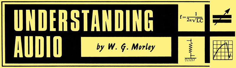
When a valve is operated in Class B, the bias point is at, or very near, its cut-off voltage, so that only amplified half-cycles appear in the anode circuit.
An alternative method of operating a valve is shown above. Here we have the same IaVg curve as we had when we previously considered Class A1 and A2 operation, but the bias point is now at, or very near, the grid cut-off voltage. We apply our input signal as before and we produce, graphically, the corresponding anode current. As may be seen, no anode current flows during the negative input half-cycle (or nearly all of the negative input half-cycle) and all we obtain at the anode is a series of half-cycles resulting from the positive half-cycles at the grid.
This method of working is known as Class B1 operation when no grid current flows during the input cycle, or Class B2 operation when grid current flows during part of the positive input half-cycle.
It is possible to operate a single valve in Class B1 or B2 as an RF amplifier if a parallel tuned circuit resonant at the frequency being handled forms the anode load. Although only half-cycles of the signal frequency appear at the anode, the tuned circuit between the anode and the HT positive rail oscillates at its resonant frequency and provides the missing half-cycles itself. At the same time, a single valve cannot be operated as an audio frequency amplifier in Class B1 or B2 because the signal voltage at the anode would be an excessively distorted version of the input signal voltage.
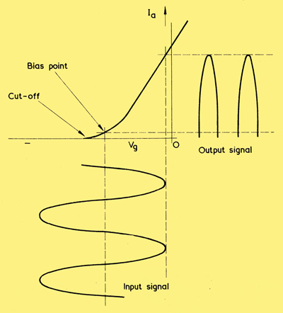
Two valves in push-pull can, on the other hand, be operated in Class B1 or B2 to provide an AF output stage, as is shown below.
A Class B push-pull output stage. Due to varying anode currents, cathode bias cannot be used and an external source of grid bias (shown here as a battery) has to be provided.
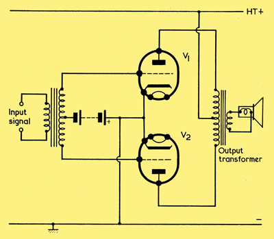
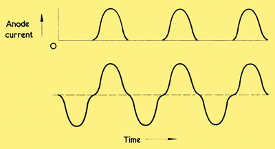
In diagram (a) below we see the anode currents for each valve over several cycles of the input signal. As is to be expected from the first graph, each anode draws current during alternate half-cycles. These anode currents flow in opposing directions through each half of the output transformer primary, whereupon they recombine to produce the original signal, as illustrated in (b). It is worth examining this process in a little more detail, as it is quite different from that occurring with the Class A push-pull amplifier we discussed in the previous chapter. If, during one half-cycle of the input signal, the grid of the upper valve of the circuit diagram is negative, then this valve is cut off and draws no current. The grid of the lower valve has a positive half-cycle applied to it and its anode current varies to provide an amplified half-cycle. When the next half-cycle commences, the grid of the lower valve goes negative and the grid of the upper valve goes positive. This time it is the lower valve which is cut off and the upper valve which provides the amplified half-cycle. Thus, on one half-cycle the upper valve is cut off and no current flows in the upper half of the output transformer primary, and on the next half-cycle the lower valve is cut off and no current flows in the lower half of the output transformer primary.
(a) With a sine wave input signal applied to the circuit, anode current in the two valves flows on alternate half cycles
(b) Since the anodes are connected to the opposite ends of a centre-tapped transformer primary, the two anode currents combine to reproduce the original signal.
Push-pull Class B1 and B2 operation does not, in consequence, offer the automatic distortion cancelling advantage which is given by Class A push-pull operation. Also, the current drawn from the HT supply is not constant, but varies considerably with input signal amplitude. If no input signal is applied both valves are cut off, or very nearly cut off, and the HT current drawn is at a minimum. When an input signal is applied, the valves draw HT current on alternate half cycles, the current increasing with signal amplitude. In consequence, it is necessary for the HT supply fed to a Class B1 or B2 push-pull stage to be well regulated.
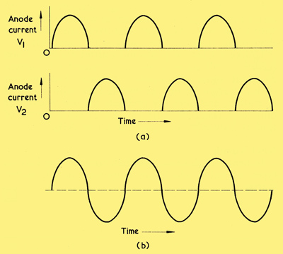
Since the point along the IaVg curve at which the valves are biased will normally be non-linear, a form of distortion can be introduced by the output stage which is shown, in exaggerated form below.
Showing in exaggerated form a type of distortion which can be introduced by a Class B output stage. The half-cycles at each anode may have the shape shown in the upper section, whereupon the combined waveform has the distortion shown below.
In this diagram sine wave half-cycles at each anode are distorted over the range where the anode current is low, with a consequent distortion in the combined waveform as illustrated in the lower waveform. It is interesting to note that the percentage distortion due to this effect increases as signal amplitude decreases. If the valves handle a large signal, the distorted section is only a small fraction of the overall waveform whereas, if the valves handle a small signal, the distorted section becomes a very large fraction of the overall waveform.
The main advantage of a Class B1 or B2 push-pull AF output stage is that it has a very high efficiency in terms of the ratio of HT power consumption to AF power output. Also, it is possible to obtain a much higher power output from two valves in a Class B push-pull output stage (especially when Class B2 working is used) than would be given by the same two valves in a Class A push-pull output stage. Class B2 working is, therefore, attractive for public address amplifiers and similar applications where a high output power is required, and particularly where batteries are used for the power supply.
Because the main reason for using a Class B push-pull AF output stage is to obtain a high power, such stages are almost always operated. in Class B2, in which grid current flows during part of the positive input half-cycles applied to the grids. The output stage has, in consequence, to be driven by a preceding power stage. Since operation in Class B2 is much more common than operation in Class B1, it can normally be assumed that reference to a Class B push-pull amplifier infers the Class B2 condition.
It will be noted that, in the circuit diagram, grid bias is provided by an external source, shown in the diagram as a battery. Cathode bias cannot be used for Class B stages because of the wide variations in anode and, hence, cathode current for different input signal amplitudes.
Class C Operation
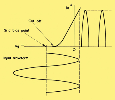
ln Class C the bias point is negative of cut-off, with the result that the valve passes current only during part of the positive input half-cycles. It is usual for the positive input peaks to pass into the grid current region, as is shown here.
A third method of working is described as Class C operation, and this is illustrated above. As may be seen, the grid bias point in this diagram is negative of cut-off so that the valve only passes anode current during part of the input positive half-cycles.
Because of the high degree of distortion introduced by Class C operation, this mode of working cannot be employed for AF amplification. on the other hand, it is very useful for RF amplification when a parallel tuned circuit forms the anode load, since it offers a high efficiency in terms of output power. Oscillatory effect in the anode tuned circuit ensures that the missing sections of the cycles appear across it, even though the valve does not itself pass anode current during these periods.
Due to the high efficiency of RF power amplifiers in Class C, this mode of operation is very frequently used for the output valve or valves of transmitters. Class C output valves are employed singly or in push-pull; in the latter case the two anodes may be coupled to the two ends of a tuned winding having a centre-tap which connects to the HT positive supply.
Greatest efficiency is obtained when the input drive to the grid of a Class C amplifier is sufficiently high to allow grid current to flow during. the more positive parts of the positive half-cycles. This is the method of working most commonly used and can be referred to as Class C2. If grid current does not flow, the mode of operation may be described as Class C1. References to RF power amplifiers normally state Class C, whereupon Class C2 operation can usually be assumed.
As is to be expected from a consideration of the manner in which it works, the HT current drawn by a Class C amplifier varies with input signal amplitude. At very low signal amplitudes (too low for correct operation) the valve is cut off all the time and it draws no anode current. When the signal input amplitude is sufficient for positive half-cycle peaks to pass beyond cut-off the valve commences to draw anode current, this current increasing as input amplitude increases.
Class AB Operation
We have seen that, in Class A, the input signal is applied over the most linear part of the IaVg characteristic. In Class B the valve is biased at (or very slightly positive of) the cut-off point so that it only amplifies the positive input half-cycles. And, in Class C, the valve is biased negative of cut-off so that it only amplifies part of the positive input half-cycles. Of these three classes, Class A and Class B can be used for AF output circuits.
A fourth mode of working is known as Class AB. As the name infers, Class AB relates to the case where the grid bias point lies between those which apply for Class A and Class B operation. Class AB working can be used with two valves in an AF push-pull output circuit, and it enables a higher power output to be achieved than would be given by the same valves in Class A.
A Class AB amplifier functions in the same manner as a Class A amplifier for small signal inputs, because the input waveform is still applied to a linear part of the IaVg characteristic. As input signal amplitude increases, the negative parts of the grid waveform become applied to the more non-linear section of the IaVg characteristic, and the distortion offered by each valve increases. However, the ability to cancel out even harmonics which is given by a Class A amplifier tends to apply here also, and this distortion is reduced. At yet higher input signal amplitudes each valve may be cut off during negative input peaks, whereupon one valve only passes anode current during these periods.
Since two valves in Class AB offer a greater power than the same valves in Class A, Class AB operation is attractive for applications where an increased distortion at high output powers is acceptable. With reasonably careful design, Class AB operation can also be used for the output stages of domestic high quality amplifiers.
Class AB stages may be divided into Class AB1 (where no grid current flows) and Class AB2 (where grid current flows during part of the positive input half-cycle). It is normal practice for the Class AB2 grid bias point to be closer to cut-off than occurs in Class AB1, and Class AB2 gives a greater power output. One sometimes encounters the statement that Class AB2 is intermediate between Class AB1 and Class B. For domestic amplifiers, Class AB1 is preferred because the output stage can be preceded by a simple voltage amplifier circuit, instead of by a power amplifier as would be required with Class AB2. Also, the distortion introduced by the output stage will be lower with Class AB1.
Unlike a Class A push-pull output stage, a Class AB push-pull stage draws an increased HT current as input signal amplitude increases. The increase in HT current is not as marked as with Class B operation, and does not preclude the use of cathode bias for Class AB1 working. An external source of grid is, however, required for Class AB2.
|