|
High voltage low current stabiliser tube operation is described.
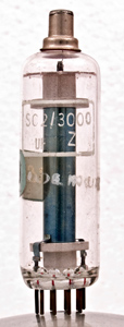
Corona Stabiliser SC2/3000.
Most readers will be familiar with cold cathode gas filled stabiliser tubes; they enable a stabilised potential in the range of about 75 to 150 Volts to be obtained at currents of the order of 10 mA. Various types of electronic equipment such as Geiger tubes, photomultiplier tubes and cathode ray tubes require a supply potential in the range 400 to 2,000 Volts or more, but the current taken is usually less than 1 mA. Although the normal type of gas filled glow discharge stabiliser tube is unsuitable for this application (unless used as a part of a complex stabiliser), a type of tube known as a corona voltage stabiliser has been developed during the last decade specifically for this type of application.
The Corona Discharge
A corona discharge can take place from an electrode which is shaped so that a high electric field strength is present at some parts of its surface. All television servicemen are familiar with the corona discharge which sometimes occurs from any point in the EHT circuit of a television receiver and which is sometimes suppressed by means of a small piece of wax. Such corona discharges do not normally occur on smooth surfaces, but readily occur from a pointed part of the surface. The end of a stray wire is a common source of such an unwanted corona discharge.
Any stray electrons (formed by cosmic rays, stray radioactive atoms, etc.) will be accelerated by the electric field until they have enough energy to form ions in the air. The electrons thus formed are in turn accelerated until they have sufficient energy to form more ions. Thus enough ions are formed to carry a small current. Some of the air molecules gain energy from the electrons in the discharge and give out light as they return to the normal state. In a darkened room one can therefore see the well-known weak glow in the region of a corona discharge; it surrounds the area of high electric field strength.
Structure
A corona stabiliser tube consists of a central wire surrounded by a cylindrical cathode, the central wire being made positive in order to render the discharge as stable as possible. Some types of corona tube have a B7G or B9A base with a top cap anode, whilst other types have a cap at each end or flying leads. Owing to the high potentials used few (if any) single-ended corona tubes have been manufactured.
Almost the whole of the potential applied to the tube appears in the region of the central anode wire where the ionisation occurs. The fact that this potential is virtually independent of the current passing through the discharge enables the corona tube to be employed for stabilisation purposes. A relatively small voltage is present between the outside of the ionisation region and the cathode. This voltage is, however, approximately proportional to the current flowing through the tube and therefore limits the voltage stability of the tube.
Circuit
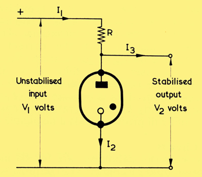
Basic circuit for a corona stabiliser
The basic circuit in which a corona stabiliser circuit is used is shown above. This type of circuit is the same as that for the common glow discharge stabiliser tube. In the case of corona stabiliser tubes, however, the applied potential, V1, is much greater than in the case of glow discharge tubes, and the currents I1 and I2 are much smaller than with the glow discharge tube circuits.
Operating Conditions
As in the case of the glow discharge stabiliser tubes, there is a minimum current which must be passed through the tube to ensure satisfactory operation. This minimum current is usually in the range of 1 to 20 μA. At smaller currents the discharge may be intermittent. The maximum current which should be passed through a corona stabiliser is usually in the range of 300 μA to 1 mA. Higher currents may cause the voltage across the tube to fall as the discharge takes the form of a 'streamer'.
The operating voltage of a corona tube is usually in the range of 350 to 7,000 Volts, although tubes with higher operating voltages can be manufactured. Two or more tubes can be connected in series if a very high voltage is to be stabilised. This will also enable stabilised voltages of less than the full voltage present across the series connected tubes to be obtained.
Corona stabiliser tubes are normally filled with pure hydrogen, since the highly mobile positive ions formed in this gas enable the rate of change of operating voltage with change of current to be kept to a minimum. In addition the use of hydrogen results in a higher maximum operating current than would be possible with other gas fillings. The operating voltage of a tube is approximately proportional to the gas pressure [2] E Cohen and R O Jenkins. 'The Characteristics and Applications of Corona Stabiliser Tubes', Electronic Engineering, Vol. 32, No. 383, Jan, 1960.; it may also be raised by increasing the diameter of the electrodes, but this will result in an increased change of operating voltage for a given change of the tube anode current.
A small amount of thorium oxide is included in some of the lower voltage corona tubes. The thorium is very weakly radioactive and provides ions which initiate the discharge. This ensures that the tubes strike promptly when a suitable potential is applied. The higher voltage tubes will strike promptly without this material.
Circuit Design
In the circuit at the top of the page, the resistor R is usually more than 1 MΩ Its value can be found by applying Ohms Law to the circuit. The current I2 is usually fixed at a value about half-way between the maximum and minimum tube operating currents. The current flowing through R is equal to the sum of I2 and the load current I3. The un-stabilised input voltage, V1, is generally about 1.2 to 1.5 times the operating potential of the tube, V2. The potential across the resistor R is equal to (V1-V2). The value of R is calculated from the voltage across it and the current passing through it.
When the circuit has been designed using these principles, it should be checked to ensure that any variations in the input voltage and in the load can be accommodated without the operating conditions of the tube passing outside the recommended limits. For example, if the input voltage is liable to increase by up to 10%, a check should be made to ensure that this increase will not result in the current through the tube exceeding the maximum permissible value. Similarly if V1 is liable to fall by 10%, a check should be made to ensure that a current at least equal to the minimum recommended tube current will continue to pass through the stabiliser tube. In addition, the un-stabilised input voltage should always be kept at least 1.1 times the operating voltage of the tube or there may be a delay in striking.
Equivalent Circuit
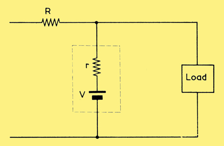
Equivalent circuit of the basic stabiliser
The equivalent circuit of the first diagram is shown in above. The components inside the dotted lines represent the tube itself. It can be seen that the tube behaves as a steady source of potential, v, in series with the resistor r. This resistor r represents the impedance of the tube. It is typically of the order of 100 kΩ the lower the value of this imaginary resistance, the better the stabilisation. The value of r varies somewhat with the current passing through the tube owing to gas heating effects.
Corona stabiliser tubes (like glow discharge tubes) cannot be connected in parallel for higher current operation. This is because one of the tubes will have a slightly higher operating potential than the other and will probably pass a negligible current.
Further Circuits
When corona stabilisers are used in series, capacitors should be connected in parallel with each tube as shown in below.
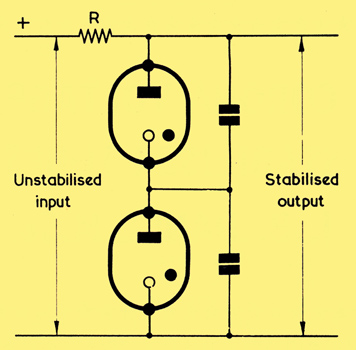
Two corona stabilisers in series
The values of these capacitors may be a few thousand picofarads. If they are omitted, relaxation oscillations may occur.
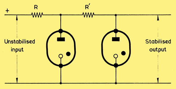
A cascade circuit
In the circuit above two corona stabilisers are employed in cascade. The variation of the stabilised output will be much less than in the simple circuit first shown for changes in the supply voltage. However, the output impedance of the circuit is similar to that of the circuit of the first circuit and therefore the change in the output voltage with change in the load will also be similar. The operating potential of the first tube should be at least about 15% above that of the second tube.
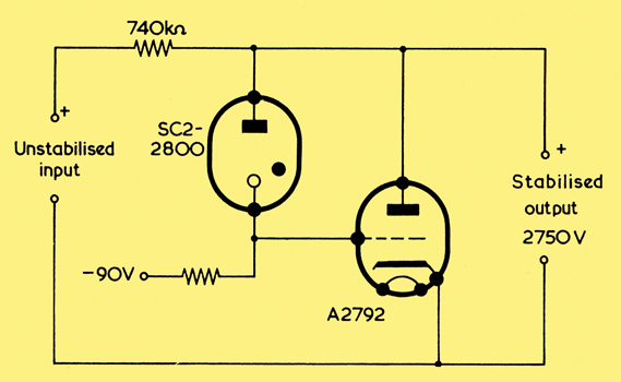
Combining a stabiliser with a triode valve provides a high voltage supply having a low output impedance. The output is approximately 2,750 Volts.
Occasionally a corona stabiliser may be used to control the grid potential of a valve. In the circuit above, V1 is a corona tube. As the input voltage varies between 3,720 and 4,280, the anode current of the triode varies from 0.29 to 1.05 mA at full load and 1.09 to 1.85 mA at no load, but the variation in the output voltage is too small to measure.
The use of the corona stabiliser in the circuit above enables almost 100% of negative feedback to be available (even at zero frequency) so that the output impedance is about 1/gm (where gm is the mutual conductance of the triode). The output impedance is typically about 500Ω which is extremely low for an EHT supply unit providing some 2,750 Volts. The current passing through the stabiliser tube is about 90 μA.
References
- R O Jenkins. 'Corona Discharge finds a useful application in Voltage Stabilisers', Electrical Review, June 14, 1963.
- E Cohen and R O Jenkins. 'The Characteristics and Applications of Corona Stabiliser Tubes', Electronic Engineering, Vol. 32, No. 383, Jan, 1960.
- J P Holland. 'Stabilised High-Voltage Supplies', Industrial Electronics, August, 1963.
|