|
MW6/2Sensibly equivalent¶ to:See also:
|
|
|
|
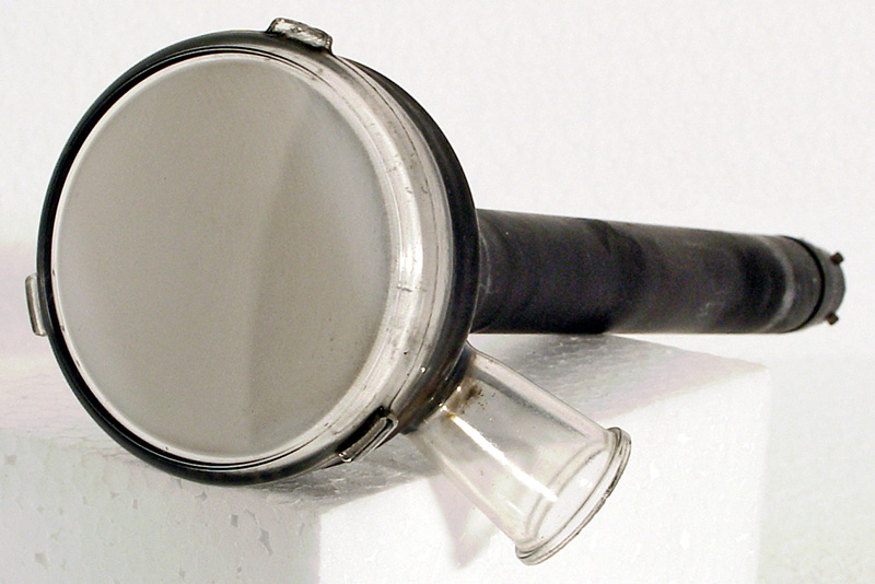
The MW6/2 (also MW6-2) is a real find. This is a monochrome projection TV tube with a metal backed screen. These tubes were found in projection television receivers of the early 1950s.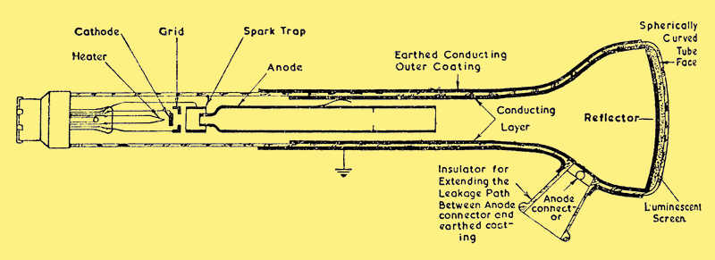
This diagram featured in the May 1950 advert.The base is a special 5 side contact design The larger of the segments of the base is the outer metallising and spark trap. The literature says that this must be grounded and that the capacitor formed by the outside metallising and the inner anode coating can be used as the EHT smoothing capacitor. This practice is now standard on picture tubes.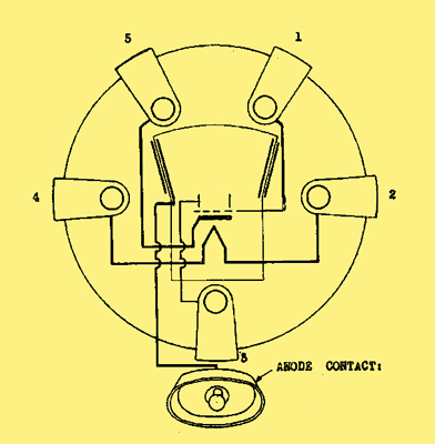
We have used the Philips pin numbering scheme but the above diagram shows the alternative way to identify the pin numbers.The deflection and focus is magnetic and the massive iron-cored yoke is visible in the insert picture. The deflection angle is 30.5 degrees, very small, but the final anode voltage is 25 kV. This is the normal final anode voltage for a late 20th century 25 inch domestic television picture tube, in a device with a raster of 40 x 55 mm maximum it is extreme. Mullard published details of how to generate the EHT required, and this incorporated a trippler on the output of the high frequency transformer.The tube shows the effects of phosphor burn and in operation the image would have had to be very bright in order to be able to project a picture of any size. The specifications insist that protection circuits are incorporated to shut off the EHT in the event of a failure of one or more timebases. Failure in this respect will instantly destroy the screen.Philps design for the optics of television projectors can be seen here in a short feature from 1943 and the article referenced above.The picture produced by back projection was typically 21 inches across the diagonal. The picture was best viewed in subdued light as was the recommendation for all viewing at the time.This tube type was used in a Philips 1400A set. The picture was back-projected onto a 21 inch screen, which was made of special plastic with very small grooves in the surface (lenticular screen). The surface grooves were designed to avoid 'hot-spots' of brightness and to improve the viewing angle.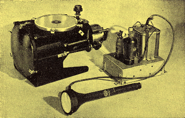
The main components of the Mullard projection TV apparatus.
The diagram is of the Schmitt Optical Box used in the set. The box contained a first concave mirror of about 150 mm diameter. The light from the tube, after reflecting from the first mirror, came back to a plane mirror inclined at 45 degrees. The tube itself passed through the centre of this plane reflector. Now travelling upwards the image was passed through a plastic anamorphic lens of some 125 mm diameter. This 'corrector plate' was designed to remove image distortions caused by the different path lengths of the centre and corners of the picture. The final mirror in the optical path was another plane reflector inclined at 45 °, this sent the image horizontally onto the screen.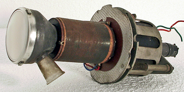
The MW6/2 seen within the deflection assembly.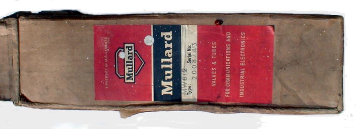
Above is a picture of an original carton from Mullard. The absence of brightly coloured card suggests that this tube was not competing for retail selection by the owner of the television.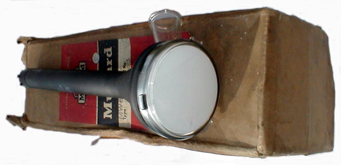
Finally we see the tube and its carton, note that unlike military devices the packaging is not massively oversized.The screen is 64 mm in diameter. A typical raster size was quoted as 34 x 46 mm. The phosphor is 57 mm in diameter on the inside of the screen.The end window envelope is 20 mm in diameter and, excluding the CT5 base pins, is 260 mm tall.Reference: Data-sheet. Type MW6/2 was first introduced in 1950. See also 1950 adverts. |
Pin Connections
| 1 | 2 | 3 | 4 | 5 | tc |  h | g1 | k | h | a1 | a |
|
|
Absolute Maximum Operating Conditions
CRT | Vh | Ah | Va | Vg | mAa | 
| 6.3 | 0.3 | 25,000 | -40 | 150uA |
|
Updated January 14, 2021.
|
|