|
Basic Design Requirements: Alternative Specifications
April 1947
Recent improvements in the field of commercial sound recording have made practicable the reproduction of a wider range of frequencies than hitherto. The useful range of shellac pressings has been extended from the limited 50-8 kHz which, with certain notable exceptions, has been standard from 1930 until the present, to a range of some 20-15 kHz. This increase in the frequency range has been accompanied by an overall reduction in distortion and the absence of peaks, and by the recording of a larger volume range, which combine to make possible a standard of reproduction not previously attainable from disc recordings. Further improvements, notably the substitution of low-noise plastic material (vinyl) for the present shellac composition, are likely to provide still further enhanced performance.
The resumption of the television service with its first-class sound quality, and the possible extension of UHF high-quality transmissions, increase the available sources of high-quality sound.
Full utilization of these recordings and transmissions demands reproducing equipment with a standard of performance higher than that which has served in the past. Extension of the frequency range, involving the presence of large-amplitude low-frequency signals, gives greater likelihood of inter-modulation distortion in the reproducing system, whilst the enhanced treble response makes this type of distortion more readily detectable and undesirable.
Reproduction of sound by electrical means involves the amplification of an electrical waveform which should be an exact counterpart of the air pressure waveform which constitutes the sound. The purpose of the amplifier is to produce an exact replica of the electrical input voltage waveform at a power level suitable for the operation of the loudspeaker. This in turn re-converts the electrical waveform into a corresponding sound pressure waveform, which in an ideal system would be a replica of the original.
The performance of an amplifier intended to reproduce a given waveform is usually stated in terms of its ability to reproduce accurately the frequency components of a mythical Fourier analysis of the waveform. While this method is convenient and indeed corresponds to the manner in which the mechanism of the ear analyses sound pressure waveforms into component frequencies and thereby transmits intelligence to the brain, the fact that the function of the system is to reproduce a waveform and not a band of frequencies should not be neglected. Sounds of a transient nature having identical frequency contents may yet be very different in character, the discrepancy being in the phase relationship of the component frequencies.
The requirements of such an amplifier may be listed as:
- Negligible non-linear distortion up to the maximum rated output. (The term 'non-linear distortion' includes the production of undesired harmonic frequencies and the inter-modulation of component frequencies of the sound wave. ) This requires that the dynamic output/input characteristic be linear within close limits up to maximum output at all frequencies within the audible range.
-
- Linear frequency response within the audible frequency spectrum of 10-20 kHz
- Constant power handling capacity for negligible non-linear distortion at any frequency within the audible frequency spectrum.
This requirement is less stringent at the high-frequency end of the spectrum, but should the maximum power output/frequency response at either end of the spectrum (but especially, at the low-frequency end) be substantially less than that at medium frequencies, filters must be arranged to reduce the level of these frequencies before they reach the amplifier as otherwise severe inter-modulation will occur. This is especially noticeable during the reproduction of an organ on incorrectly designed equipment where pedal notes of the order of 16-20 Hz cause bad distortion, even though they may be inaudible in the sound output.
- Negligible phase shift within the audible range. Although the phase relationship between the component frequencies of a complex steady-state sound does not appear to affect the audible quality of the sound, the same is not true of sounds of a transient A nature, the quality of which may be profoundly altered by disturbance of the phase relationship between component frequencies.
- Good transient response. In addition to low phase and frequency distortion, other factors which are essential for the accurate reproduction of transient waveforms are the elimination of changes in effective gain due to current and voltage cut-off in any stages, the utmost care in the design of iron-cored components, and the reduction of the number of such components to a minimum. Changes in effective gain during 'low-frequency' transients occur in amplifiers with output stages of the self-biased Class AB type, causing serious distortion which is not revealed by steady-state measurements. The transient causes the current in the output stage to rise, and this is followed, at a rate determined by the time constant of the biasing network, by a rise in bias voltage which alters the effective gain of the amplifier.
- Low output resistance. This requirement is concerned with the attainment of good frequency and transient response from the loudspeaker system by ensuring that it has adequate electrical damping. The cone movement of a moving-coil loudspeaker is restricted by air loading, suspension stiffness and resistance, and electro-magnetic damping. In the case of a baffle-loaded loudspeaker, the efficiency is rarely higher than 5-10%, and the air loading, which determines the radiation, is not high. In order to avoid a high bass-resonance frequency, the suspension stiffness in a high-grade loudspeaker is kept low, and obviously the power loss in such a suspension cannot be large. Electro-magnetic damping is therefore important in controlling the motion of the cone. This effect is proportional to the current which can be generated in the coil circuit, and is therefore proportional to the total resistance of the circuit. Maximum damping will be achieved when the coil is effectively short-circuited, hence the output resistance of the amplifier should be much lower than the coil impedance.
- Adequate power reserve. The realistic reproduction of orchestral music in an average room requires peak power capabilities of the order of 15-20 Watts when the electro-acoustic transducer is a baffle-loaded moving-coil loudspeaker system of normal efficiency. The use of horn-loaded loudspeakers may reduce the power requirement to the region of 10 watts.
The Output Stage
An output of the order of 15-20 watts may be obtained in one of three ways, namely, push-pull triodes, push-pull triodes with negative feedback, or push-pull tetrodes with negative feedback. The salient features of these methods are of interest.
Push-pull triode valves without the refinement of negative feedback form the mainstay of present-day high-fidelity equipment. A stage of this type has a number of dis-advantages. With reasonable efficiency in the power stage such an arrangement cannot be made to introduce non-linearity to an extent less than that represented by about 2-3% harmonic distortion. The output/input characteristic of such a stage is a gradual curve as in Fig. 1 (a).
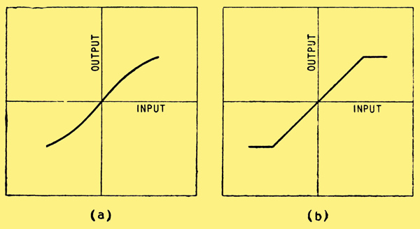
Fig. 1. Output/input characteristics (a) without feedback (b) with negative feedback.
With this type of characteristic distortion will be introduced at all signal levels and inter-modulation of the component signal frequencies will occur at all levels. The inter-modulation with such a characteristic is very considerable and is responsible for the harshness and 'mushiness' which characterizes amplifiers of this type. In addition, further non-linearity and considerable inter-modulation will be introduced by the output transformer core. If the load impedance is chosen to give maximum output the load impedance/output resistance ratio of the amplifier will be about 2, which is insufficient for good loudspeaker damping.
It is difficult to produce an adequate frequency response characteristic in a multi-stage amplifier of this type as the effect of multiple valve capacitances and the output transformer primary and leakage inductances becomes serious at the ends of the AF spectrum.
The application of negative feed- back to push-pull triodes results in the more or less complete solution of the disadvantages outlined above. Feedback should be applied over the whole amplifier, from the output transformer secondary to the initial stage as this method corrects, distortion introduced by the output transformer and makes no additional demands upon the output capabilities of any stage of the amplifier.
The functions of negative feedback are:-
- To improve the linearity
of the amplifier, and output
transformer.
- To improve the frequency response of the amplifier and output transformer.
- To reduce the phase shift in the amplifier and output trans- former within the audible frequency range.
- To improve the low-frequency characteristics of the output transformer, particularly defects due to the non-linear relation between flux and magnetizing force.
- To reduce the output resistance of the amplifier.
- To reduce the effect of random changes of the parameters of the amplifier and supply voltage changes, and of any spurious defects.
A stage of this type is capable of fulfilling the highest fidelity requirements in a sound reproducing system. The output/input characteristic is of the type shown in Fig. 1 (b), and is virtually straight up to maximum output, when it curves sharply with the onset of grid current in the output stage. Non-linear distortion can be reduced to a degree represented by less than 0.1% harmonic distortion, with no audible inter-modulation. The frequency response of the whole amplifier from input to output transformer secondary can be made linear, and the power handling capacity constant over a range considerably wider than that required for sound reproduction.
The output resistance, upon which the loudspeaker usually depends for most of the damping required, can be reduced to a small fraction of the speech coil impedance. A ratio of load impedance/output resistance (sometimes known as 'damping factor') of 20-30 is easily obtained. Kinkless or beam tetrodes used with negative feedback can, with care, be made to give a performance midway between that of triodes with and without feedback. The advantages to be gained from the use of tetrodes are increased power efficiency and lower drive voltage requirements.
It must be emphasized that the characteristics of the stage are dependent solely upon the character and amount of the negative feedback used. The feedback must remain effective at all frequencies within the AF spectrum under all operating conditions, if the quality is not to degenerate to the level usually associated with tetrodes without feedback. Great care must be taken with the design and operation of the amplifier to achieve this, and troubles such as parasitic oscillation and instability are liable to be encountered.
When equipment has to be operated from low-voltage power supplies a tetrode stage with negative feedback is the only choice, but where power supplies are not restricted, triodes are preferable because of ease of operation and certainty of results.
It appears then that the design of an amplifier for sound reproduction to give the highest possible fidelity should centre round a push-pull triode output stage and should incorporate negative feedback.
The most suitable types of valve for this service are the PX25 and the KT66. Of these the KT66 is to be preferred since it is a more modern indirectly-heated type with a 6.3-volt heater, and will simplify the heater supply problem. Triode-connected it has characteristics almost identical with those of the PX25.
Using a supply voltage of some 440 Volts a power output of 15 Watts per pair may be expected.
The Output Transformer
The output transformer is probably the most critical component in a high-fidelity amplifier. An incorrectly designed component is capable of producing distortion which is often mistakenly attributed to the electronic part of the amplifier. Distortion producible directly or indirectly by the output transformer may be listed as follows:-
- Frequency distortion due to low winding inductance, high leakage reactance and resonance phenomena.
- Distortion due to the phase shift produced when negative feedback is applied across the transformer. This usually takes the form of parasitic oscillation due to phase shift produced in the high frequency region by a high leakage reactance.
- Intermodulation and harmonic distortion in the output stage caused by overloading at low frequencies when the primary inductance is insufficient. This is primarily due to a reduction in the effective load impedance below the safe limit, resulting in a very reactive load at low frequencies. This may cause the valves to be driven beyond cut-off since the load ellipse will tend to become circular.
- Harmonic and intermodulation distortion produced by the non-linear relation between flux and magnetizing force in the core material. This distortion is always present but will be greatly aggravated if the flux density in the core exceeds the safe limit.
- Harmonic distortion introduced by excessive resistance in the primary winding.
The design of a practical transformer has to be a compromise between these conflicting requirements.
At a low frequency f b, such that the reactance of the output transformer primary is equal to the resistance formed by the load resistance and valve AC resistances in parallel, the output voltage will be 3 dB below that at medium frequencies. At a frequency 3 f b the response will be well maintained, the transformer reactance producing only 200 phase angle. Similarly at the high frequency end of the spectrum the response will be 3db down at a frequency f t such that the leakage reactance is equal to the sum of the load and valve AC resistances. Again at a frequency f t/3 the response will be well maintained.
If then the required frequency range in the amplifier is from 10-20 kHz, f b may be taken as 3.3 Hz and f t as 60 kHz. A transformer which is only 3 dB down at frequencies as widely spaced as these would be difficult to design for some conditions of operation, and where this is so the upper limit may be reduced, as the energy content of sound at these frequencies is not usually high. The limiting factor will be the necessity of achieving stability when feedback is applied across the transformer, i.e., that the loop gain should be less than unity at frequencies where the phase shift reaches 180°.
To illustrate the procedure, consider the specification of an output transformer coupling two push-pull KT66 type valves to a 15 Ω loudspeaker load.
- Primary load impedance: 10,000 Ω
- Turns ratio: (10,000/15)1/2 = 25.8:1 :I
- Effective AC resistance of valves = 2,500 Ω
- Low frequency Response
- Parallel load and valve resistance 2,500 x 10,000 / 12,500 = 2,000 Ω
- f b = 3.3 Hz (ωb≊ 21) response should be 3 db down
- Primary incremental inductance
- L = 2,000/21 = 95 H
- High-frequency Response
- Sum of load and AC resistances
- = 10,000 + 2500
- = 12,500 Ω
- At f t = 60 kHz (ωt = 376,000) response should be 3 db down.
- ∴ Leakage reactance = 12,500 / 376
- = 33 mH.
A 20-watt transformer having 10 primary and 8 secondary sections and using one of the better grades of core material can be made to comply with these requirements. Winding data will be given in an appendix (see page 11).
Some confusion may arise when specifying an output transformer as the apparent inductance of the windings will vary greatly with the method of measurement. The inductance of an iron-cored component is a function of the excitation, the variation being of the form shown in Fig. 2. The exact shape of the curve is dependent on the magnetization characteristic for the core material.
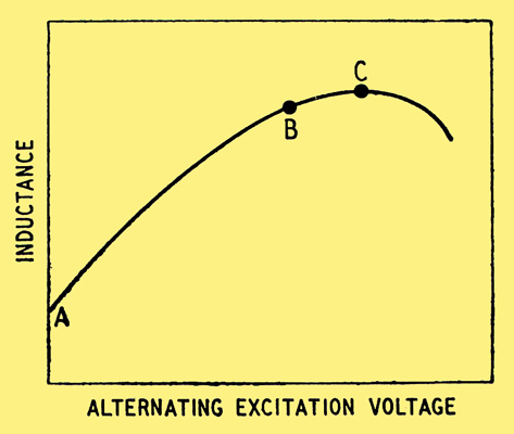
Fig. 2. Variation of iron-cored inductance with AC excitation.
The maximum inductance, corresponding to point C occurs when the core material is nearing saturation and is commonly 4-6 times the 'low excitation' or 'incremental' value at A, which corresponds to operation near the origin of the magnetization curve. In a correctly designed output transformer the primary inductance corresponding to the voltage swing at maximum output at 50 Hz will lie in the region of B in Fig. 2.
In specifying the component, the important value is the incremental inductance corresponding to point A, since this value determines the frequency response at low outputs.
Phase Shift
The reduction of phase shift in amplifiers which are to operate with negative feedback is of prime importance, as instability will result, should a phase shift of 1800 occur at a frequency where the vector gain of the amplifier and feedback network is greater than unity. The introduction of more than one transformer into the feedback path is likely to give rise to trouble from instability. As it is desirable to apply feedback over the output transformer the rest of the amplifier should be R-C coupled.
Alternative Circuits
Although the amplifier may contain push-pull stages it is desirable that the input and output should be 'single ended' and have a common earth terminal. Three circuit arrangements suggest themselves.
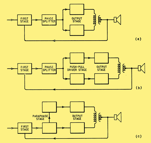
Fig. 3. Block diagrams of circuit arrangements discussed in the text.
The block diagram of Fig. 3 (a) shows the simplest circuit arrangement. The output valves are preceded by a phase splitter which is driven by the first stage. The feedback is taken from the output transformer secondary to the cathode of the first stage. This arrangement is advantageous in that the phase shift in the amplifier can easily be reduced to a low value as it contains the minimum number of stages. The arrangement, however, has a number of disadvantages which render it unsuitable. The input voltage required by the phase splitter is rather more than can be obtained from the first stage for a reasonable distortion with the available HT voltage, and in addition the phase splitter is operating at an unduly high level. The gain of the circuit is low even if a pentode is used in the first stage, and where a low-impedance loudspeaker system is used, insufficient feedback voltage will be available.
The addition of a push-pull driver stage to the previous arrangement, as in Fig 3 (b), provides a solution to most of the difficulties. Each stage then works well within its capabilities. The increased phase shift due to the extra stage has not been found unduly troublesome provided that suitable precautions are taken.
The functions of phase splitter and push-pull driver stage may be combined in a self-balancing 'paraphase' circuit giving the arrangement of Fig. 3 (c). The grid of one drive valve is fed directly from the first stage, the other being fed from a resistance network between the anodes of the driver valves as shown in Fig. 4. This arrangement forms a good alternative to the preceding one where it is desirable to use the minimum number of valves.
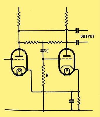
Fig. 4. 'Paraphase' circuit combining the functions of phase splitter and push-pull driver stages.
|