|
Reducing inter-electrode Capacitance and Transit Time

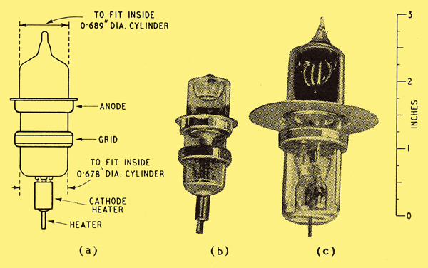
Types of valve construction (a) 'acorn', (b) pressed-glass base, (c) conventional pinch seal and moulded base.
During the past ten or fifteen years considerable progress has been made in improving the high-frequency performance of triodes and pentodes by reducing the inductance of the leads to the electrodes. One of the first attempts in this direction was the 'acorn' valve, which was designed with a very small electrode system, the leads from which projected as radial pins passing through the all-glass envelope. It is interesting to note that the earliest forms of this type of valve employed planar electrodes in 1933, similar in some respects to those which will be mentioned later. However, this construction was abandoned in favour of a very small cylindrical electrode system when 'acorns' were eventually produced and marketed. The 'acorn' type of valve, while enabling a considerable improvement to be obtained in the effective amplification at very high frequencies, has proved to be a difficult manufacturing proposition and has been superseded by valves with conventional electrode systems, mounted on flat glass bases through which pass the lead-out wires, which themselves form the valve pins. Two forms of such designs are represented in present-day commercial products in the button seal pressed-base valves, commonly known as the miniature, and the ring seal moulded-base type. In all these valves the electrode lead-out wires themselves form the connecting pins and the necessity for an external base with separate pins has been obviated.
These glass-based valves represent a big step forward in valve design, and there seems little doubt that the majority of receiving valves in the future will be mounted on this form of base. Quite apart from the advantages of this construction for high frequency operation, it has led to a reduction in size and freedom from loose base troubles, which, under some conditions, occur with the cemented plastic base. Furthermore, with large-scale production the cost of manufacture of some forms of pressed glass base valves may be less than with earlier designs.
The image above shows an 'acorn' valve, a modern valve on a pressed-glass base and a valve mounted on the conventional glass pinch, a feature which owes its origin to the electric lamp.
In a wide-band amplifier it is normal for the dynamic resistance of the circuits to be of a comparatively low order and several considerations arise in the design of a suitable valve for high gain combined with low noise in such amplifiers.
The gain of a single stage of a wide-band amplifier is proportional to the ratio of the mutual conductance (gm) to the sum of the input capacitance (Ci), the output capacitance (Co) and the stray capacitances (Cs). It is important therefore to make this ratio as high as possible. In addition, for successful high frequency operation the inter-electrode capacitances should be kept small, in order to keep as much as possible of the circuit external to the valve, and the electron transit time should be reduced to a minimum.
Now it can readily be shown that the requirements of high ratio of mutual conductance to capacitance and of low electron transit time require a high ratio of electron current density to grid-cathode spacing. The further requirement of low inter-electrode capacitance necessitates a small cathode area. Thus the best performance is likely to be obtained with a valve having a small cathode area, small grid-cathode spacing and operating at a high current density.
The ultimate sensitivity of a high-gain amplifier depends on its signal-to-noise performance. If the gain of the first amplifier stage of a receiver is more than about 5 dB then most of the noise output is contributed by the first stage. The amount of noise contributed by a valve is usually regarded as being equivalent to that generated in an imaginary resistance Rs in the grid circuit of the valve. Rs is known as the equivalent noise resistance of the valve and is approximately inversely proportional to the mutual conductance. If R1 is the dynamic resistance of the input circuit, then it can be shown that the signal-to-noise ratio is a function only of the ratio R1/Rs and will increase as this ratio increases.
Now R1 cannot be increased indefinitely owing to the inherent losses in circuit components so that the only way to improve the signal-to-noise performance is by increasing the mutual conductance of the valve.
For frequencies above a few hundred megacycles per second a greater decrease in lead inductance proves necessary than has been achieved in the conventional concentric cylindrical arrangement of electrodes, and this improvement has been achieved by making the electrodes integral with metal discs which pass through the envelope and which may be directly connected to cavity resonators if desired.
These valves are known as the disc-seal type and such are capable of operation at frequencies up to about 4,000 MHz. The valves employ planar electrodes which allow very small inter-electrode spacings to be achieved, permitting a high mutual conductance from a small cathode area and a high ratio gm/Cg-k.
An example is the Osram and Marconi disc-seal triode type DET23 in which the mutual conductance is 7.0 mA/volt at an anode current of 10 mA, and the total input and output capacitances including the discs which pass through the envelope are 2.4 pF and 1.1 pF respectively, of which the discs themselves account for about 0.7 pF in each case. Thus: Cg-k is 1.7 pF and Ca-g is 0.4 pF. This high ratio of mutual conductance to input capacitance is better than has hitherto been achieved with concentric electrode arrangements, and is due to the fact that the spacings are small only at the operating surfaces of the electrodes.
Examples of disc-seal triodes (a) outline of DET23, (b) E1599 (CV273), (c) E1368 (CV90).
These disc-seal valves (shown above) which were designed primarily for ultra-high frequencies will be seen to satisfy the wide-band amplification requirements set out above. It therefore seemed desirable to employ a similar electrode arrangement in valves designed for more general use in the UHF range, such as valves mounted on pressed glass bases with the pins forming the lead-in wires. Valves of this type are easier to use and less costly than the disc-seal valves.

Experimental parallel electrode triode (EI7I4 = CV408) on a pressed glass base.
A typical triode of this class is the experimental type EI74 and is illustrated above.
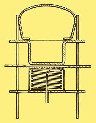
The very small grid-cathode spacing employed (0.003 in) necessitates the use of extremely fine and closely spaced wires for the grid, and the design of the grid (Fig. 4) is one of the principal features of valves of this type. In the conventional type of electrode system in which the grid wires are located on two separating rods the wires themselves must be sufficiently strong to carry the separate rods so that the whole structure is rigid enough for handling during the assembly of the valve electrodes without risk of distortion, and this sets a lower limit to the diameter of wire which can be employed. In planar electrode valves a departure from convention has been made, which enables rugged grids to be manufactured with wires as small as 0.0006 in.
Grid assembly of planar-electrode valve.
The grid is in the form of a metal plate pierced by a circular aperture across which the grid wires are stretched, while the cathode and anode are the end surfaces of two short cylindrical members supported from or integral with a relatively thick and therefore rigid plate. These plates and the grid frame are located in slotted mica bridges which serve to hold the electrodes in the correct relative positions. Stray capacitances between the electrodes are in this way reduced to a minimum, only the operating surfaces of the electrodes being in close proximity. The leads connecting the electrodes to the pins in the valve base are also well spaced and contribute little to the total capacitances. The electrode assembly for this type of valve is shown in Fig. 5.
The very small diameters of grid wire possible with this construction allow adequate grid dissipation for amplifiers and for low-power oscillators. Furthermore, the grid frame serves to radiate heat and thus minimizes the risk of primary grid emission.
Electrode assembly in-the type EI7I4 triode.
The characteristics of the EI714 are as follows:-
- Filament voltage 6.3 V
- Filament current 0.5 A
- Anode voltage 250 Vmax
- Amplification factor 40
- Mutual conductance 8.0 mA/V measured at anode voltage 150 and anode current 10 mA.
Capacitances:-
- cathode cold/hot (Ia = 10 mA)
- Cg-k 1.6 pF/2.9 pF
- Cg-all except anode 2.6 pF/3.7 pF
- Ca-all except grid 1.1 pF
Equivalent noise resistance 500 ohms (Ia = 10 mA).
These characteristics undoubtedly represent the best performance which has been obtained with a triode operating at frequencies of the order of 45 MHz, covering a bandwidth of 10 to 15 MHz/sec.
|