|
The circuit chosen for this efficient 2-valve receiver incorporates the well known Hartley method of applying reaction which is controlled by a small variable capacitor.
The cost of the materials used is under #3, but by substituting cheaper components the price can be reduced to about #2, without seriously reducing the efficiency. This cost does not include headphones, valves and batteries. All components actually used in the set described are of the highest quality and are thoroughly recommended.
The set is easily constructed and no soldered joints are necessary.
(2) The Panel.
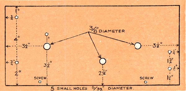
The panel is of ebonite 3/4 inch thick and measures 14in. x 7in. It may be bought from any radio store and it would be advisable for those who do not possess suitable drIlls to have the 10 holes drilled at the shop when making the purchase. The positions of the holes will depend, to a certain extent, upon the components used. The sizes and positIons indicated are suitable for the components recommended.

(3) Screwing Panel to Baseboard.
The baseboard is of 1/2 inch soft wood and measures 14in. x 7 1/2in. The panel is fixed to the baseboard with two 1in. No.6 brass or iron countersunk screws, the necessary holes in the panel being countersunk with a rose drill. The screw holes are drIlled with a 5/32in. drill 1/4 of an Inch from the bottom edge of the panel and 2 1/2in. to 3in. from each end.
The panel is then secured as shewn; the operation will be greatly facilitated if the panel is supported on a pile or books or boxes whIlst the screws are being inserted.

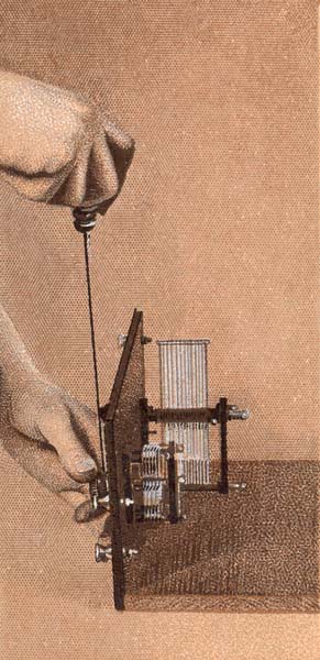
(4) Fixing the Tuning Capacitor.
The variable capacitor is an "Ormond' .0005 micro Farad S.L.F. No.3 and is fitted into the 3/8in. hole nearest the left of the panel when viewed from the front. The fixing is by the well-known "one hole' method, the instrument being held in place by a single nut, which is secured firmly by means of a suitable spanner. Care must be exercised when handling to avoid bending or damaging the thin vanes.
The slow motion dial is also shewn on the bench.
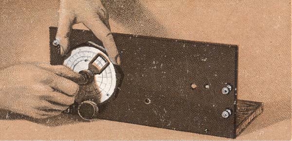
(5) Fixing Slow Motion Dial.
This picture shows how the 'Ormond' slow motion dual indicator dial is fixed. A coin is used to tighten the dial on the capacitor spindle. Full printed instructions are issued with the dial when sold.
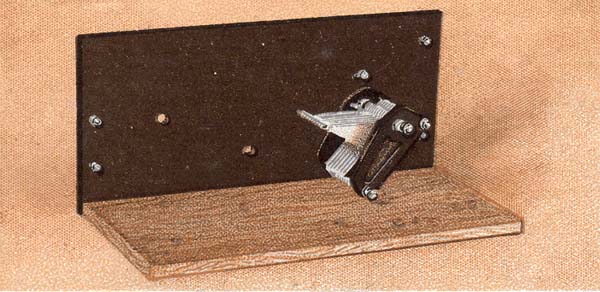
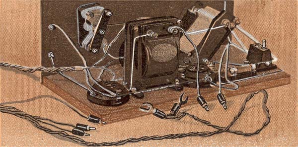
(6) Panel with Capacitor Fixed.
This is a view of the baseboard and back of panel with tuning capacitor in position. The four terminals also have been fitted. These are standard 4 B.A. Brass W.O. pattern terminals, but may be obtained nickel plated if desired. The two nearest the capacitor are (top) aerial and (bottom) earth connections. The remaining two are for headphones or loud speaker.
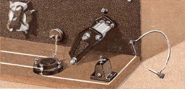
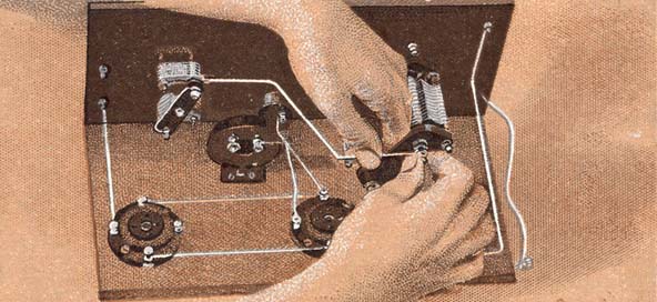
(7) Fixing Reaction Capacitor.
This small variable capacitor has a capacity of .0001 micro Farad and is made by Messrs. Ormond Ltd. It is fixed in a similar manner to the tuning capacitor. The control knob which has a pointer fixed to it is secured on the spindle by a grub screw, which is tightened up as shewn. The instrument has two sets of fixed vanes, these should be connected together with a length of tinned copper wire, as is used to wire up the other components, the two ends being secured under the nuts which hold on the end plate.
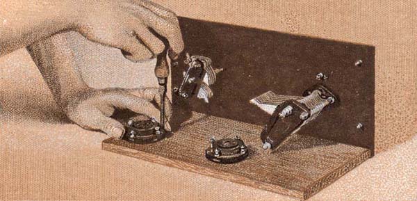
(8) Fixing Valve Holder.
The two valve holders are next fixed to the baseboard with ordinary screws 3/4in. No. 6 are suitable. 'Lotus' valve holders were used. The one being screwed down in the picture should be fixed with its edge 1 inch from the back edge of the baseboard and 1/2 inch from the end. The other one 4 1/2 inches towards the other end of the baseboard. The positions are more clearly indicated on card No. 11. Care must be taken to see that the filament terminals are in line and that the anode terminals are to the left when viewed from the back.
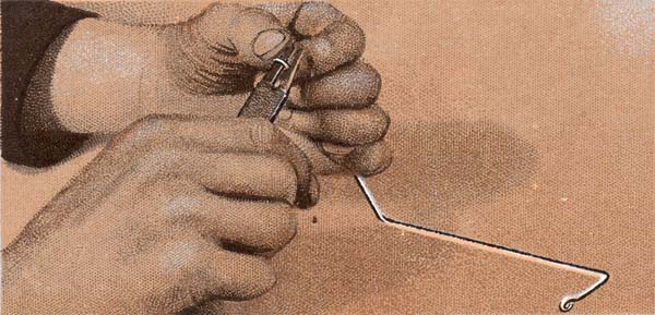
(9) Bending Loop In Wire.
Three yards of No. 16 SWG tinned copper wire should be obtained, and the lengths required for connecting up the various components cut off as required. Any slight bends can be removed by slightly stretching the wire. One end being held in a vice and the other in the jaws of a pair or pliers. Loops to fix on the various terminals are easily bent as shewn. A pair of round nosed pliers only being required.
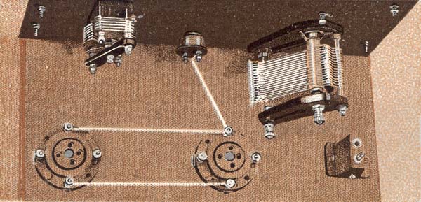
(10) Inside of Cabinet.
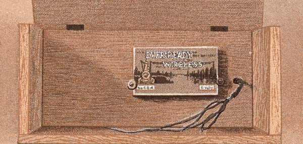
The cabinet may be as simple or elaborate as taste and pocket decree. Oak or mahogany is suitable and the material should be 1/2 inch thick. A 5ft. length of 7 1/2in. wood is sufficient to make a cabinet with plain butt joints fixed with 1 inch No. 6 screws. The illustration shows how the grid bias battery (9 volt) is secured to the back of the cabinet. Two large washers being used to enable the two 1 1/4in. No. 6 screws to hold the battery in posItIon.
(11) Wiring the Filament Circuit.
A filament rheostat is fitted into the remaining hole in the panel. This instrument shewn is a "Microstat' but any make of panel mounting rheostat will do. The resistance will depend upon the valves used. Advice upon this point will be readily given at the place of purchase.
5 ohms is suitable for the valves recommended. The filament terminals of the valve holders are connected in parallel, and the side nearer the panel is wired to either one of the terminals on the rheostat.
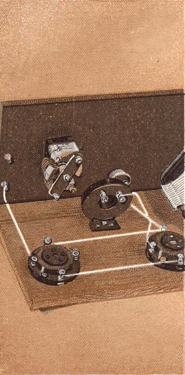
(12) The Earth Terminal Connections.
A baseboard mounting coil holder is fitted two inches from the back edge and 1/2 inch from the end of the baseboard as shewn. The earth (bottom) terminal is then connected to the filament terminal nearest the back edge of baseboard on the first valve holder. A 6in. length of insulated flexible wire is also attached to the earth terminal, the other end of this flex is attached to the split connecting plug which is supplied with the centre tapped coil (see card 22).
(13) Tuning Coil Connections.
The Grid Capacitor (Dubilier .0003 micro Farad) is now screwed to the baseboard between the coil holder and first valve holder. One terminal is joined to the grid terminal of the valve holder, the other to the fixed plates of the tuning capacitor, and also to one side of the coil holder and to the aerial terminal.
The other terminal of coil holder is connected to the centre (moving vanes) of the tuning capacitor.
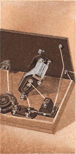
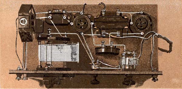
(14) The Anode Connections.
Here is shewn the high frequency choke ('Igranic') which is fixed to the baseboard as near to the filament rheostat as possible without touching). One terminal of the H.F. choke is joined to the anode (or plate) terminal of the first valve holder. The anode terminal of the second valve holder may now be connected to the lower of the two phone terminals. All terminals should be screwed up tightly.
(15) Reaction Capacitor Connections.
This picture indicates the connection from the moving (centre) vanes of the reaction capacitor, being fixed to the moving vanes of the tuning capacitor. Care must be taken to see that this wire is bent to clear the moving vanes of the tuning capacitor, as they are moved by rotating the knob on the front of the panel.

(16) Reaction Capacitor Connection. (Contd.).
The connection from the fixed vanes of the reaction capacitor is made to the same terminal on the HF choke that is wired to the anode terminal of the first valve holder.
This connection is indicated by the finger which is shewn touching the wire.
The grid leak of 2 meg. ohms (Dubllier) is also shewn in the clips provided on the grid capacitor.
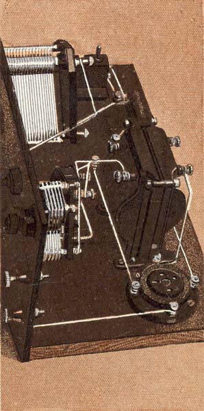
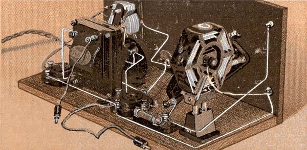
(17) The LF Transformer.
The LF (low frequency) transformer, a Ferranti AF3 has now been fixed between the two valve holders and clear of the filament wiring. The terminal marked "Plate' is wired to the free terminal of the HF choke. The terminal on the transformer which is marked "Grid' is connected to the grid terminal of the second valve holder.
This completes the wiring with the exception of the battery leads, which are Of insulated flexible wire.
(18) Grid Bias Leads.
Two lengths of coloured insulated flexible wire, one 6in. long (black) and one 9in. (red) are fixed to black and red "wander' plugs (Lisenin Positive Grip). The other end of the black wire is joined to the terminal on the transformer which is marked "Grid Bias'. The red wire is similarly screwed under the filament terminal of the first valve holder to which the earth terminal is connected.
(19) Battery Connections.
The set is now ready for the High Tension and Low Tension flexible leads to he fixed. A five-way cable may be purchased complete with plugs, but for economy one may be prepared. Obtain a 6ft. length of thick red and black twin flex, and three 3ft. lengths of single flex. These may be or smaller gauge and or different colours to avoid confusion. The colours used in the set described are gold, green and brown.
A hole large enough to take the bunch of five wires must be bored through the back of cabinet as shewn on card No.10.
(20) Battery Connection. (Contd.).
The five wires are now twisted into a cable leaving 8-inch ends loose for connections to the terminals in the set. 4 inches may be cut off the black and brown wires, the bared ends of both these wires are clamped under the filament terminal of the second valve, as shewn in the pIcture. The three remaining ends are bared and are connected as follows: Red to the spare terminal on the filament rheostat, Green to the +H.T. terminal on the transformer. Gold to the top earphone terminal.
(21) Battery Connections (Contd).
The five battery connections are now all fixed to their terminals inside the set. The other end of the 5-way cable is passed through the hole in back of cabinet.
The red and black wires should be terminated with spade terminals of the same colours, and the brown. green and gold leads should have wander plugS attached. Care should be taken to ensure that the ends or the wires make good contact with the plugs, and spade terminals. Lisenin Positive Grip plugs and terminals are recommended.
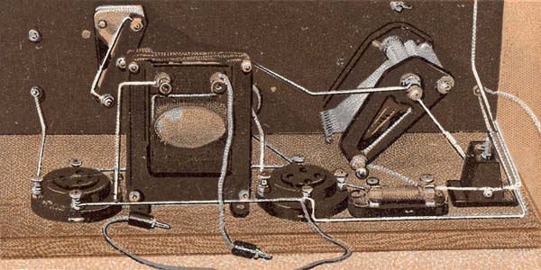
(22) The Inductance Coil.
The inductance coil shewn is a No.60 (Edison-Bell Radio) centre tapped. The plug on the short flexible lead from the earth terminal is plugged into the socket as shewn, With the average aerial the tuning range will include most of the broadcast wave band.
For 5XX and Radio-Paris stations a coil No.250 will be required. This also must be centre tapped.
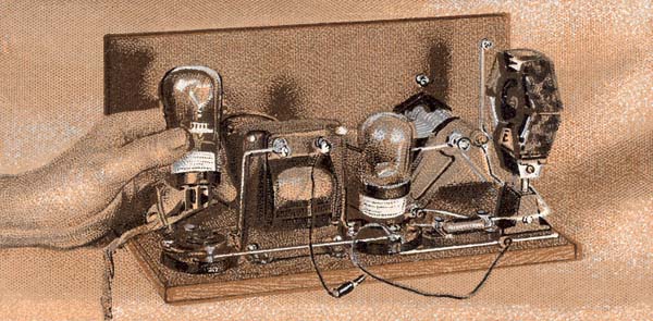
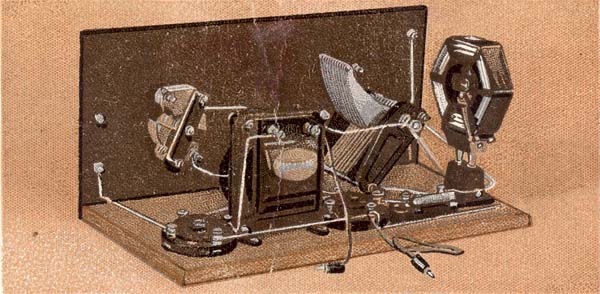
(23) The Valves.
2-volt Mullard valves are recommended. The first (detector) is a P.M.1. H.F. valve. This is shown in position. The valve being placed in its holder is the low frequency amplifier and is a P.M.2.
The set is now ready to be slipped into its cabinet and is ready to work when connected to aerial, earth, batteries and headphones.
(24) Connecting Up.
The slack in the battery cable should be pulled through the hole in the cabinet, and the grid bias plugs inserted in the battery which is fixed to the inside of the cabinet. The red plug is pushed firmly into the socket marked + and the black plug in the fourth socket from the + (positive).
The black and red flex will be long enough to reach the floor (on which the 2-volt accumulator usually stands) and the spade terminals are joined to the respective terminals of the accumulator.
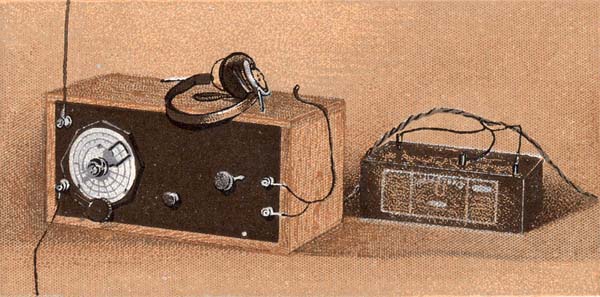
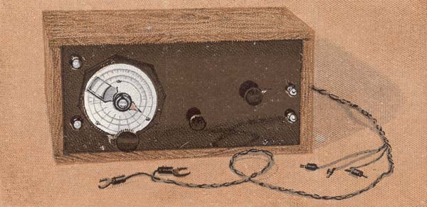
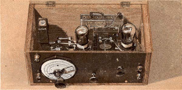
(25) The Set Finished.
The three short leads of the battery cable go to the High Tension battery. The brown wire to the negative (-), the green to 60, and the gold to the highest number (100 or 120), according to the size of the battery in use. The local station and 5XX will "come in' at fair loud speaker strength, and over a dozen distant stations have been logged in as many minutes.
The final image is the actual reverse of the card complete with original text. The actual cards are 66 mm x 34 mm and quite difficult to read.
|