|
The Triode Valve
The diode valve is essentially a rectifier, turning AC into DC, whether these be large mains voltages or relatively small signal voltages, as in the detection of modulated radio signals, for example. True, it can perform other useful functions as well, but one thing it cannot do is amplify a signal, For this we need to develop the basic device further. We mentioned earlier Lee de Forest's work with a diode, in which he had inserted a wire grid between cathode and anode in order to control the anode current. This was the first triode valve – triode obviously meaning 'three electrodes', although he actually called it an 'audion'. The construction of a modem triode is shown in (a) below, together with its circuit symbol, (b).
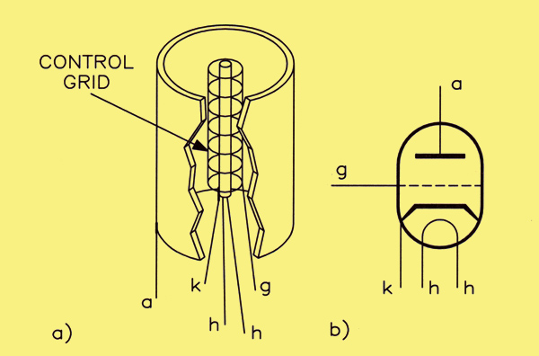
(a) Construction of a triode valve, (b) circuit symbol for a triode valve.
Based on what we have already seen for the diode, it has an indirectly heated cathode and an outer anode electrode. The third electrode is known as the control grid. It is quite open in form, so that there are relatively vast areas for the electrons to pass through on their way to the anode. It is, quite literally, in the vast majority of cases, no more than a single spiral of wire. In use, the control grid is taken to a potential that is negative with respect to that of the cathode. As a result, there is a negative potential gradient between the cathode and the control grid (tending to repel electrons), and a positive potential gradient from grid to anode, so that electrons that do get through the grid are accelerated to the anode where they are collected.
If the negative potential of the control grid is fairly small, then most electrons emitted by the cathode have sufficient energy to counter the repelling force of the grid and make it to the anode; a small percentage are turned back to the cathode so that, overall, the anode current is actually reduced in value by the presence of the grid. The more negative the grid is made then the more influence it is able to exert on the electrons which are attempting to reach the anode. Eventually, it will be able to turn back all electrons when its negative potential is large enough. The anode current is then said to be 'cut off, and the value of grid voltage that just causes this condition is termed the 'grid cut-off voltage' – all very reasonable!
Another way to picture this effect is to see the electrons leaving the cathode as being subject to two conflicting influences – the negative repulsion of the control grid and the positive attraction of the anode. Because the control grid is very close to the cathode (the anode is far away by comparison), it can exercise quite a strong influence with only a small negative voltage. The higher the energy possessed by an electron, the more chance it has of accelerating through the open wires of the grid and reaching the anode. At some point, the influence of the grid will outweigh that of the anode, no matter what the energy level of the electrons, and the current flow will stop entirely. It's worth mentioning at this point that this is exactly how a typical Field Effect Transistor works, and which came into existence out of the need for a semiconductor which could do the sort of jobs that the old valves used to do!
The Triode Mutual Characteristics
The behaviour described above can be understood also from the mutual characteristics. which are graph plots of anode current versus grid voltage for different values of anode voltage. A set of these is shown.
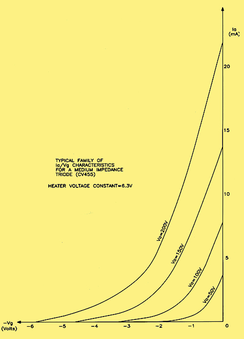
Family of mutual characteristics for a CV455 triode.
the anode voltages being chosen at 50. 100. 150 and 200 V. These are actual examples for the CV455 (ECC81) double-triode valve.
Note that the higher the anode voltage. the larger the negative grid voltage has to be in order to produce a given anode current or to cut the valve off completely. For example. if the grid voltage. Vg. is 0 V then the anode current is 4 mA for an anode voltage of 50 V. but is 22 mA when the anode voltage is increased to 200 V. Also. when the anode voltage is only 50 V, the grid cut-off voltage is about -2 V, but when the anode voltage is 200 V, -6 V is needed to cut off the anode current. From the fore going explanation, this is just the behaviour that we should expect.
Mutual Conductance
The ability of the control grid to control the anode current is expressed by a second valve parameter, known as the mutual conductance, gm. This is seen defined in the illustration above as the slope of a characteristic, and is given by:
gm = (change in anode current) / (corresponding change in grid voltage)
This is an important parameter, because it is also useful for predicting the triode's performance as an amplifier. The units traditionally used for measuring gm are mA/V (milliamps per volt) although these days, no doubt, we ought to call them mS (milli-Siemens). Old habits die hard though, as no doubt you will notice! The value of gm for the CV455 (ECC81) is 4 mA/V.
The Triode Anode Characteristics
Another set of characteristics are those plotted for anode current against anode voltage for a selection of values of grid voltage. In principle these are similar to the output characteristics of a transistor (Ia/Vc for values of Ib), though the shape is quite different. From these it is possible to see how, for a given value of grid voltage, the anode current varies with anode voltage. There is clearly a direct, almost linear, relationship.
The illustration below shows a set of these characteristics for the CV455 (ECC81) triode. As for the diode valve, the reciprocal of the slope of any curve is the anode slope resistance, ra, of the valve. For this particular valve, it has a value of about 13.5kΩ.
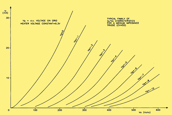
Family of anode characteristics for a CV455 triode.
Cathode Bias
We have already said that, in practice, the grid is taken to a voltage that is negative with respect to the cathode, This will be explained more fully when amplifiers are discussed but, for now, perhaps it is not too unreasonable to accept this basic idea, This would seem to imply that we need an actual negative DC supply and, in fact, in the early days of valve technology, such a supply was provided, In battery operated receivers a special battery was employed which comprised a number of 1.5 V cells with brass tubular connections, into one of which a banana plug would be fitted to select the required value of grid bias voltage. Such a method is neither desirable nor essential in the case of mains-operated equipment, and a different philosophy allows us to dispose of the separate supply completely. It works as follows. The terms positive and negative are purely relative on/s. 1/vo voltages may be both positive with respect to some reference. say 0 V. However. the smaller of the two voltages can be said to be negative with respect to the other one. Thus if we wish to make the grid of the valve negative with respect to the cathode, we only need to make the cathode positive with respect to the grid, to achieve the same object. How this is done is illustrated below.
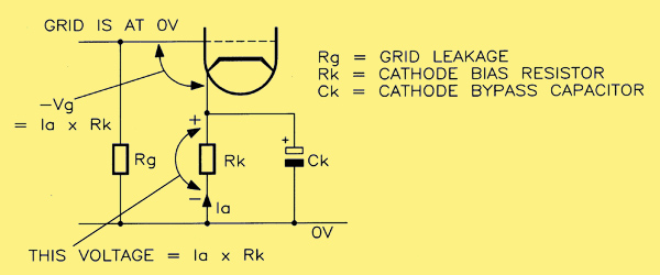
Method for deriving cathode bias for a valve.
The control grid is connected to 0 V via a high value resistor (typically 1 MΩ) known as the grid leak. Since no current flows in this resistor there can be no voltage drop across it and, therefore. the grid must be also at 0V as far as DC is concerned. The cathode. in contrast. has a resistor inserted in series, which is bypassed by a capacitor to avoid negative feedback effects (exactly as is practice with transistor amplifiers). The product of this resistance value and the current flowing in it (the anode current Ia produces a voltage drop. A moment's thought shows that the value of this voltage drop must equal the value of grid bias required, since the cathode will then be positive with respect to the grid by this amount. For example, if the grid bias voltage is to be -2 V when the anode current is 10 mA, then the cathode resistor must have a value equal to (2 / l0) kΩ, which equals 200Ω, which can be rounded up to 220Ω.
|