|
- The First Radio Valve
- Why Was it Called a Valve
- Modern Radio Valves
- The Diode as a Detector
- The Diode as a Rectifier
- Mazda U403
- Mazda D1
Edison while conducting one his multitudinous experiments on incandescent lamps observed that after a period of use the inner surface of the glass bulb became coated with a thin dark film. This he deduced as being caused by particles having been emitted or thrown off from the filament when it was heated. Pursuing this line he found that this clouding could be stopped by placing a metal plate between the filament and the glass bulb. To his amazement he found that a current flowed between the filament and the plate. This is now known as the Edison Effect.
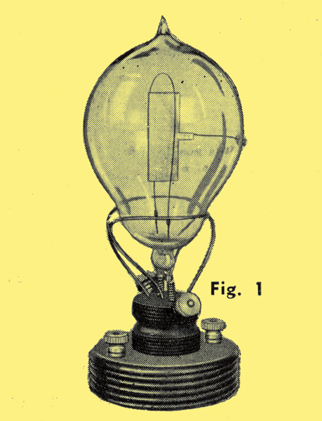
In 1889 Professor J A Fleming, who was at that time technical adviser to the Edison Swan Company, started his famous exhaustive study of what Edison had observed. This work culminated in his epoch-making invention, in 1904, of the first radio valve, (Fig. 1).
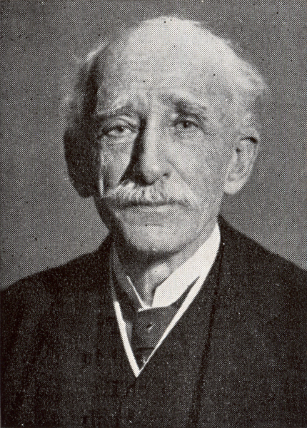
Professor John Ambrose Fleming
This, the first efficient detector of radio signals, was made from a carbon filament lamp in which a nickel plate was mounted between the legs of the filament and fixed to a wire sealed through the side of the bulb. (Fig.1) An explanation of its action is given later.
Why Was It Called A Valve
To understand why Fleming called a detector of radio signals a valve we must see what happens when a carbon or (more usually) a metal filament is heated. All substances, metals or non-metals, are built up of elementary units called atoms.
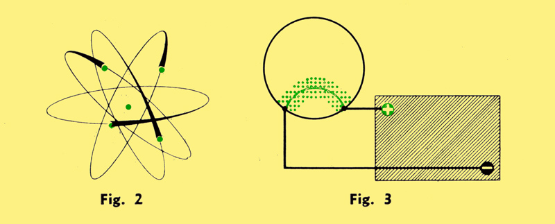
These atoms are not solid particles as might be supposed but are in fact like tiny solar systems. Each atom contains a central core, and round this core are whirling numbers of electrons, like planets in their orbit. (Fig. 2).
Early in the century Sir Joseph J. Thomson showed that these electrons were themselves actual particles of electricity which carried a negative charge.
The word negative and positive are survivals from the earliest days of electricity, when the current was thought to flow from the positive terminal of the battery to the negative. The term negatively charged was applied to the electron because it was attracted by the positively charged plate or anode.
The atom is electrically neutral; that is, there are equal numbers of positive and negative charges, but when it loses an electron it becomes positively charged, since it now has more positive than negative charges. Similarly an atom with excess of electrons is negatively charged. The attraction between positive and negative results from the attempt by Nature to restore the electrical balance of a charged atom by transfer of electrons from the negatively charged region to that positively charged.
The flow of what we call an electric current, Thomson showed to be due to the movement of billions of these tiny particles.
When a wire, such as the filament of a lamp, is heated, the atoms become violently agitated and some of the heat energy is imparted to the electrons. This causes them to leave the orbits in which they are moving, and when the filament is in vacuum, the outermost electrons will fly out of the atom altogether into the space surrounding the wire (Fig. 3), thus the hot filament becomes surrounded almost immediately by a cloud of negatively charged electrons.
If we insert a plate in the bulb near the filament and connect it to the positive terminal of a battery, the negative terminal being connected to the filament, the positively charged plate will attract the electrons (Fig. 4).
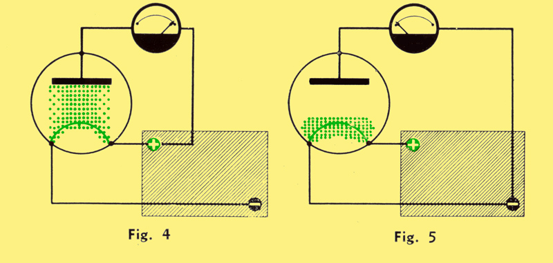
Thus they will move across the space towards the plate, flow down the connecting wire to the battery and flow back to the filament again. We have caused a steady movement of electrons from the filament to the plate. In other words, electric current flows.
Alternatively, if the anode were connected to the negative of the battery (Fig. 5), no current would flow because the negative potential on the anode would repel the negatively charged electrons.
The filament-plate arrangement thus acts as a non-return valve in which a flow can take place only from the filament to the plate. This is why Fleming called it a thermionic valve, the word thermionic meaning movement of particles by heat.
Our American friends call valves vacuum tubes, which is perhaps a more general title to cover all the types which have been designed.
Modern Radio Valves
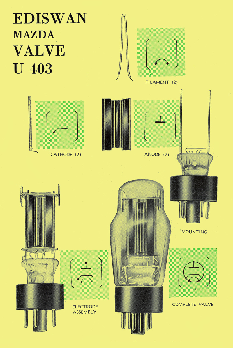
This photograph shows one of the modern valves which have been developed from Fleming's original
The Cathode
This is the name given to the hot metal from which the electrons are emitted. In the early valves, and in some modern valves, it is in the form of a thin filament of tungsten wire which is heated nearly white hot by passing through it a current from a battery.
It was soon found that certain chemicals could be made to give a more copious emission of electrons if they were coated on the wire, and further, that the wire need be heated only to a dull red to obtain the emission. This discovery improved the life of the valve and made it more efficient.
The next development which took place was to coat the chemicals on a nickel tube and heat this tube by means of a wire inside, but insulated from it. This wire could then be connected through a transformer and operated from the supply mains. This type of cathode is called indirectly heated.
The Anode
This is the plate to which the electrons are attracted after leaving the cathode - in fact it is still called the plate in America, although it has changed in appearance from the original flat plate of Fleming's valve.
In most modern valves it takes the form of a hollow box which surrounds the cathode, instead of a plate with the cathode round it. Thus it can attract the maximum number of electrons. The distance between the anode and the cathode is usually made small to reduce the amount of electrical force required to move the electrons across. The anode and cathode are held rigidly to prevent any relative movement which would disturb the even flow of the electrons.
The Electrode System
The anode and the cathode are referred to as the electrodes of the valve, and valves with two electrodes are called diodes.
A double diode is a valve containing two diode systems in one bulb, that is two anodes and two cathodes. More usually, one cathode is employed to supply electrons to the two anodes, but the valve is still called a double-diode.
It is important to note that in an indirectly heated valve the cathode and heater together are considered as one electrode.
The Diode as a Detector
We have called the diode valve a detector of radio signals. Radio signals, whether Morse Code, speech, or music, are transmitted through space by electromagnetic waves which, arriving at the receiving aerial, produce currents in the circuit connected to it.
These currents flow backwards and forwards, or oscillate (Fig. 6) at a very high frequency - several hundred thousand times a second - and the speech or music (Fig. 7) which is transmitted is caused to vary this amplitude of oscillation as shown in Fig. 8.
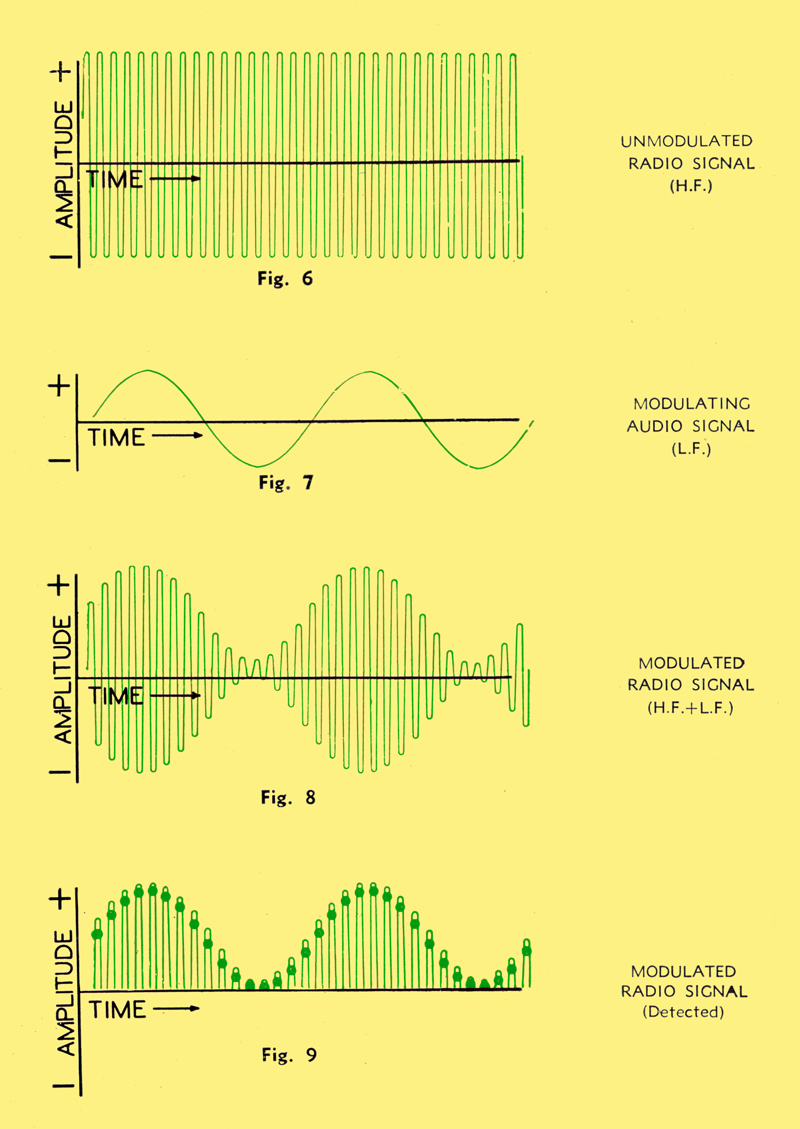
The high frequency current in the transmitter and in the receiver acts as a carrier of the lower frequency currents produced by the microphone, and for this reason the electromagnetic wave which is transmitted is called the carrier.
Now if this carrier current were applied to the loudspeaker or telephones of the receiver, we should hear no sound, for two reasons:
- The diaphragm of the loudspeaker cannot vibrate as quickly as the oscillations of the carrier current.
- It could respond to the varying amplitude of the carrier, but since at any instant the positive mean value has an equal and opposite negative mean value (Fig. 8) the one cancels out the other and the effect on the loudspeaker is nil. This is where the diode comes in.
If the high frequency current in the receiver is passed through a diode, the one-way action will allow only the positive halves of the carrier wave to pass through to the other side of the circuit, and this will change the wave into a series of rapid one-way pulsations, the individual height of which is varied according to the lower (carried) frequency. (Fig. 9).
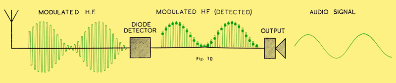
The loudspeaker diaphragm now receives these impulses and is able to respond to their mean value (shown dotted in Fig. 9), which is, of course, a reproduction of the original Low Frequency signal from the microphone. Hence the train of events in Fig. 10 ensues.
The Diode as a Rectifier
Although we have called the diode a detector in the preceding section, a better word for it is rectifier, that is, a straightener of oscillating current.
Most receivers nowadays are operated from the 50 cycles AC (50 Hz alternating current) mains, in which the current oscillates, or changes its direction of flow 50 times per second.
The word oscillating is usually applied to currents which change direction very rapidly, that is, several thousand times a second. Currents which change only 50 or so times a second are called alternating currents.
To operate a radio valve satisfactorily the positive potential which is applied to the associated circuit must be steady in value, and therefore, one of the operations in the mains receiver must be to change the alternating current mains supply into a steady current (DC-direct current) before it is applied to the valve circuits.
This is done by applying the AC supply through a transformer to a diode, such as the U403 (Fig. 11), hence cutting off the lower halves of the waves as in the case of detection. This is called Half-Wave rectification. The top halves of the wave will cause unevenness in the current flow, owing to the gaps between the pulses of current. So we connect a condenser (capacitor) across the output from the diode, as shown in Fig. 12.
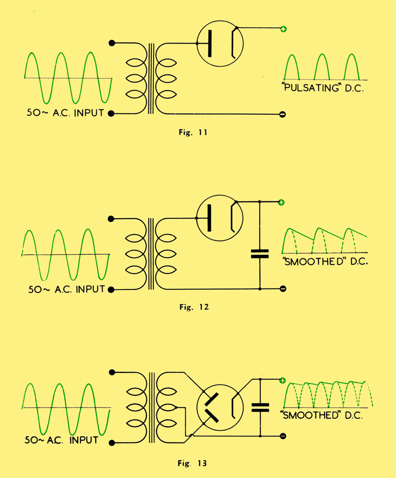
This capacitor acts as a reservoir, which stores energy during the time the current is flowing, and discharges it in the no current periods.
The wave of the current is thus made more smooth, as shown in the illustration, and after adding more smoothing devices the ripple can be so reduced as to give a direct, unvarying current.
A more efficient method is to use a double diode, such as the UU5, connected so as to rectify alternate halves of the wave (Fig. 13). This has the effect of filling up the gaps between the unidirectional pulses in the output of the half-wave rectifier, enables greater energy output to be obtained and further reduces the ripple. This is Full-Wave rectification.
The valve shown in the photograph (page 5) is a U403 Half-Wave power rectifier. It has two anodes and two cathodes, but they are so joined as to act as one valve with electrodes double the size. A Full-Wave rectifier (UU5), however, has two separate anodes and cathodes.
Ediswan Mazda Valve U403
AC/DC Mains Half-Wave Rectifier.
RATING:
Heater Voltage 40.0
Heater Current (Amps.) 0.2
Maximum Anode Voltage (RMS) 250
Maximum Output Current (mA) 120
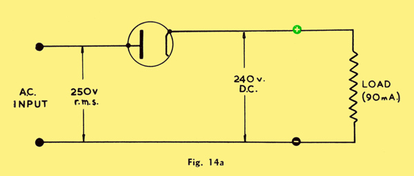
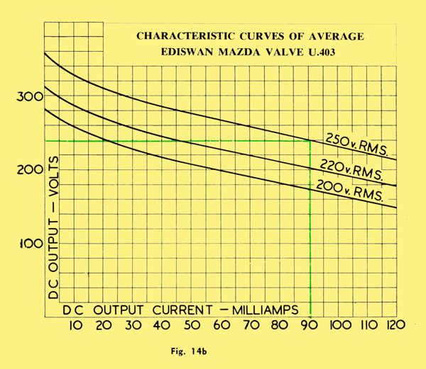
To understand what the characteristic curves (Fig. 14b) tell us, we must first consider the way in which the rectifier is used. Fig. 14a shows a circuit of a conventional half-wave rectifier and a load, from which the smoothing circuits mentioned earlier have been omitted for the sake of clarity. In this case the load is depicted as a resistance, but obviously it can take any form, for example a receiver or an amplifier. Let us assume that 250 V RMS is applied from the AC mains to the input of the circuit shown. Knowing the current which is to be drawn, we can- then determine the output voltage from the curve in Fig. 14b.
Suppose we need 90 mA to operate the load, then from the curve, as indicated in green, the output voltage can be read off as 240 Volts DC
Ediswan Mazda Valve D1
Television Single Diode D1
RATING
Heater Voltage 4.0
Heater Current (Amps.) 0.2
Maximum Peak Anode Current (mA) 50
Maximum Peak Inverse Anode Voltage 500
DIMENSIONS
Maximum Overall Length 46 mm.
Maximum Diameter 11 mm.
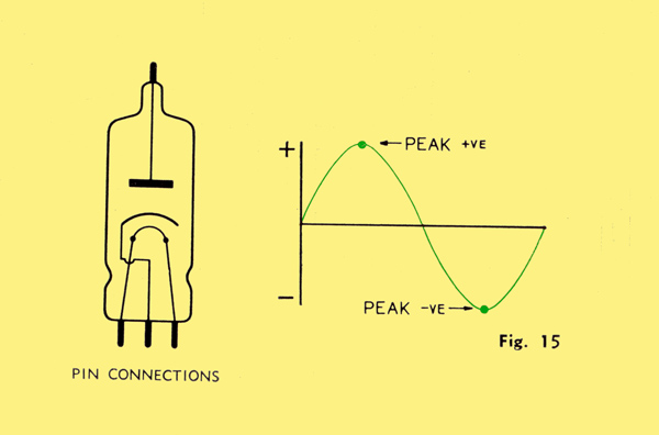
The peak value of a current or voltage is the maximum value attained at the extreme top or bottom of the curve. (Fig. 15).
The peak inverse voltage is the highest voltage which can, without damaging the valve, be applied in the opposite direction to that which assists the flow of electrons.
Return to Electrons Contents List
|