|
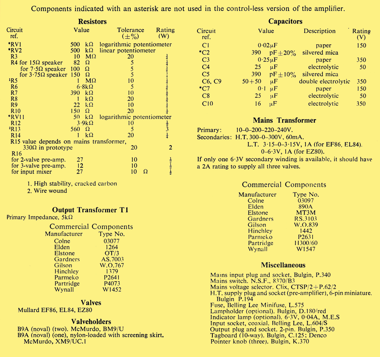
Prototype of three Watt amplifier
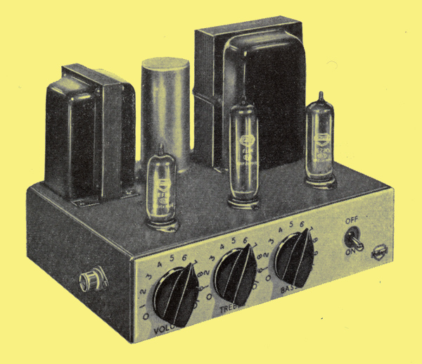
Underside view of prototype 3-3 amplifier
The circuit described in this chapter has been developed to meet the demand for a simple amplifier of reasonably high quality. The amplifier, which is operated from AC mains, uses three Mullard valves: an EF86, an EL84 and an EZ80.

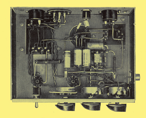
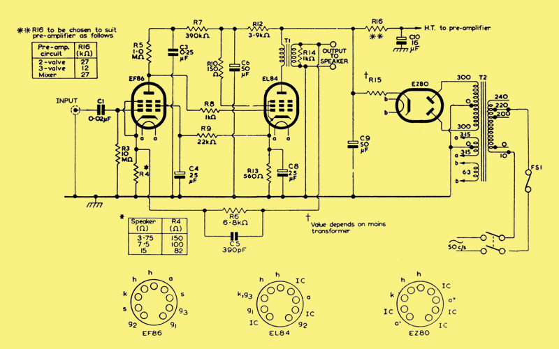
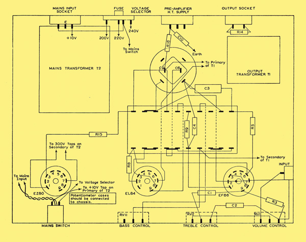
Circuit diagram of the amplifier with tone controls
Circuit diagram of the amplifier without tone controls
The comparatively high sensitivity of the amplifier (100 mV for 3 W) permits the use of all types of crystal pick-up head and allows, if required, the use of equaliser networks between the head and amplifier. The output terminations of the circuit are suitable for almost all kinds of loudspeaker, but, although the circuit is designed to make the most effective use of the single output valve, the best possible results will only be achieved if a suitably housed high-quality speaker is used.
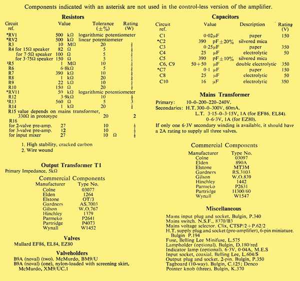
List of components. An * indicates for tone control version only
CIircuit Description
Because of the inherently high level of distortion with single-ended output stages, appreciable negative feedback around the output stage is necessary to produce an output of acceptable quality. At the same time, an overall sensitivity of 100 mV is required if the amplifier is to be suitable for use with any type of crystal pick-up head. (The attenuation resulting from pick-up equalisation with passive RC networks must also be borne in mind.)
Open loop-gain characteristics
The basic sensitivity of the circuit without feedback should be about 1 μV in order that the desirable level of feedback (about 20dB) can be provided. From considerations of stability, this feedback should be taken around the minimum number of stages.
The EF86 in the voltage-amplifying stage is used under conditions approaching those of starvation operation. With a high value of anode load resistance (R5 is l MΩ) and reduced values of anode and screen-grid voltage, the gain of the stage is raised two or three times above that obtained under normal operating conditions. This increase is attributable mainly to the fact that, because the voltage at the anode of the EF86 is very low, direct coupling can be used between this anode and the control grid of the EL84 in the output stage. Thus the shunt loading on the anode circuit of the EF86 is least at low and medium frequencies.
The use of direct coupling between the stages necessitates a higher cathode voltage in the output stage than is required with RC coupling. The value of R13 is thus greater than is usual for the cathode resistance. The screen-grid voltage for the EF86 is, taken from the cathode of the EL84. In this way, negative DC feedback (which is essential in a directly coupled circuit to stabilise the operating conditions of both stages) is applied to the voltage amplifier.
Negative AC feedback is applied from the secondary winding of the output transformer to the cathode of the EF86. In the circuit with tone controls, this feedback loop incorporates the bass-boost control, the amount of feedback being changed continuously at low frequencies as the resistance of the control potentiometer RV11 is varied. In the simplified version of the circuit, the control RV11 is omitted, and the feedback loop consists of R6 and C5 only.
Provision for volume and treble control is made at the input of the amplifier. The potentiometers RV1 and RV2 constitute these controls respectively. In the control-less version of the amplifier, the output is taken directly to the capacitor C1 in the control-grid, circuit of the EF86.
The power supply uses the EZ80 in combination with a mains transformer meeting the specification given below. The resistor R15 between the cathode of the EZ80 and the reservoir capacitor C9 is for voltage control. The anode of the EL84 is supplied from C9, and the screen-grid is supplied through another filter network R12, C6. The HT supply for a pre-amplifier is taken from C9. Extra smoothing is provided by R16 and C10.
Construction and Assembly
See also an example of a professionally built 3-3 amplifier.
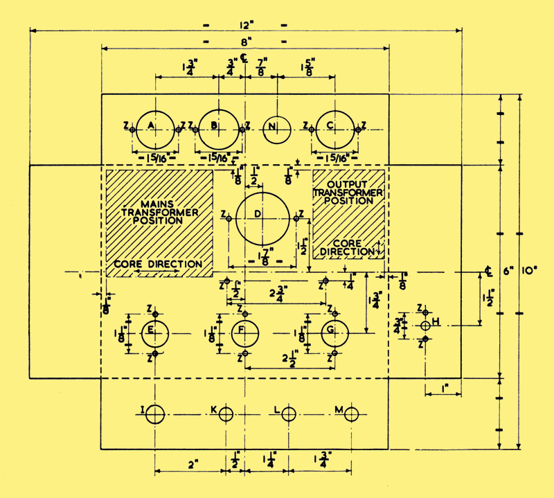
Chassis details. Bend up through 90° along dotted lines
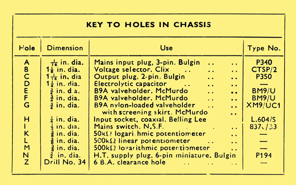
Key to holes in chassis
Chassis details of the amplifier are given above. For the control-less version, holes for the potentiometers will not be required. The chassis can be cut from one piece of 16 SWG aluminium sheet, 12 in. long and 10 in. wide. A bottom cover plate to the amplifier is not necessary.
Suggested layout of components
A suitable arrangement of the components in the amplifier with controls is shown above. The position of the components on the tag-board is given below.
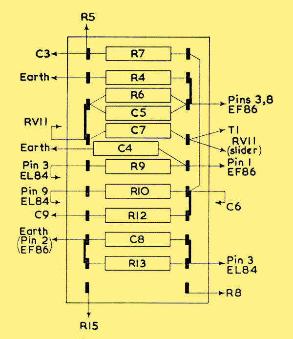
Layout of components on the tag-board. For the control-less version, the potentiometers RVl, RV2 and RV11 and the capacitors C2 and C7 are omitted. The capacitor Cl will be connected directly to the input socket, and the feedback path will be completed by connecting the appropriate junction of R6 and C5 to the speaker terminal.
If the can of the double electrolytic capacitor is used as the negative side, then it should be isolated from the chassis. The earth connection to the chassis should be made at the input socket only.
The mains transformer should have an HT rating of 300-0-300 V, 60 mA, and it is preferable, though not essential, that a separate LT winding (6.3 V) be used for the EZ80 rectifier. This is indicated in the circuit diagram, and also in the list of components.
Performance
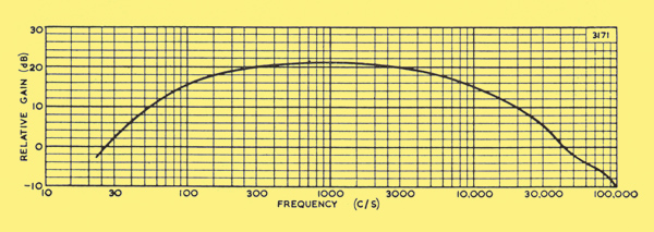
Frequency Response
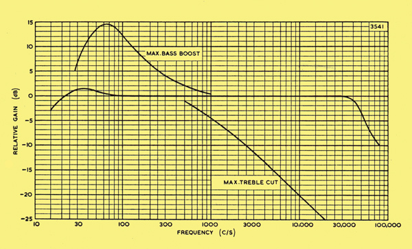
Frequency response of amplifier showing relative gain without application of tone controls, and also showing relative gain with maximum application of tone controls
With the treble and bass controls in their minimum effective positions, or with the control-less circuit, the frequency response is essentially flat from 35 Hz to 30 kHz. With maximum application of the respective controls, a treble cut of 20 dB is available at 10 kHz, and a bass boost of 10dB is available at 70 Hz. The bass boost is obtained by reducing the main feedback at low frequencies by means of RV11 and C7.
Distortion
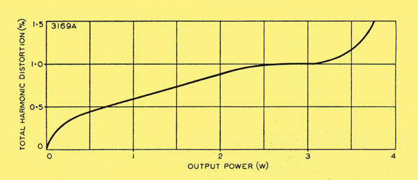
Variation of total harmonic distortion with output power
The relationship between the total harmonic distortion and the output power is shown. It will be seen that, for a typical amplifier, for outputs above about 3.5 W , the distortion increases rapidly. This indicates the point beyond which over loading of the amplifier occurs.
Output Impedance
The output impedance of the amplifier for a loudspeaker load of 15 Ω is less than 1.5 Ω. This gives an adequate damping factor of more than 10 (that is, GT 15/1.5).
DC Conditions
The DC voltages at points in the equipment should be tested with reference to the table. The results shown in this table were obtained using an Avometer No. 8.
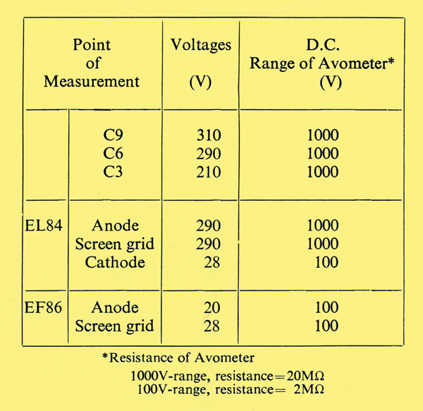
DC conditions as measured with an AVO 8 (20,000 Ω/Volt)
|