|
Mercury Vapour Rectifiers
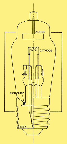
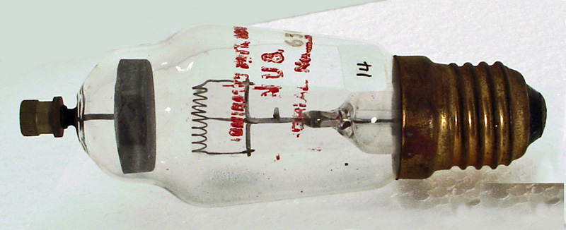
A typical mercury vapour rectifier.
The essential difference between a vacuum rectifier and a mercury vapour rectifier is that the latter contains a certain amount of mercury, partly in liquid form and partly vapour, depending upon the temperature conditions. When a potential difference is applied between the anode and the heated cathode an electron stream flows in the normal manner, and in their passage from the cathode to the anode electrons will collide with mercury vapour molecules and produce a state of ionisation. The positive ions on account of their high mass and the low potential gradient move towards the cathode at a relatively low velocity, and will neutralise the space charge existing between the cathode and the anode.
In a vacuum valve the presence of the space charge has the effect of reducing the space current and of necessitating the use of relatively high anode potentials. To remove the space charge entirely in a vacuum rectifier would require the application of very high anode voltages which might damage the valve by excessive anode dissipation and liberation of gas. The cathode, moreover, would be rapidly destroyed by the bombardment of positive ions which would be travelling at an extremely high velocity on account of the large potential between the anode and the cathode.
The introduction of mercury vapour into the valve and the consequent neutralisation of the space charge without the need for very great anode potentials, permits the anode current of the mercury vapour valve to approach the total emission of the cathode, whilst avoiding the risk of cathode damage from high-velocity bombardment.
The potential difference which is necessary between the anode and the cathode in a mercury vapour rectifier in order to produce a satisfactory ionisation of the vapour is usually less than 20V. Thus, provided the anode voltage is of that order, the anode current will be unrestricted by the presence of a space charge and will only be limited by the emission available from the cathode. The principal property of the mercury vapour rectifier therefore is that it will pass a relatively large current with only a very small potential difference across it. The very low value of the rectifiers resistance and its practically constant voltage drop require the use in practice of a limiting resistance in series with the rectifier.
If it should happen that the anode voltage were applied to the rectifier, before an adequate amount of mercury had been vaporised, the flow of electrons from the cathode to the anode would result in an insufficient number of positive ions to neutralise the space charge. The internal resistance would be excessively high and the voltage drop across the rectifier would accordingly be high also. Under these conditions, the velocity of such positive ions as did exist would be sufficient to cause cathode damage by bombardment, and partly for this reason a pre-heating time is always specified in the case of mercury vapour rectifier.
By pre-heating time is meant the period during which the cathode is heated before the application of the anode voltage. Mercury vapour rectifier cathodes are normally of the high current low voltage type having a considerable thermal capacity, and an appreciable time is required for the cathode to reach its operating temperature. Subsequent to this the heated cathode will cause the evaporation of a certain amount of mercury until a new state of equilibrium exists inside the bulb. If the valve has not been recently used, or if it has been disturbed so that the mercury may have splashed on to the emissive coating of the cathode, it will be necessary to take still greater care that an adequate pre-heating time is allowed. In the latter event, for instance, the presence of liquid mercury actually on the cathode will result in very rapid evaporation and an excessive mercury vapour pressure around the cathode. If the anode voltage were applied whilst this condition persisted, arcing would take place between the electrodes and the valve would be damaged. In these exceptional cases it will generally be found that the manufacturer recommends the pre-heating time of between 15 and 30 minutes but for the routine starting of valves in regular use, the pre-heating time is less than this and may even be as short as a minute. In either case the length of the pre-heating time depends upon the size of the valve and upon the room temperature and it is safest to make sure that the recommended times for any particular type are known.
It is a common practice, and a very good practice, to make use of automatic time delay switches to take care of the necessity for a pre-heating time. These switches are generally thermal in principle and their release time, which is obviously determined by the rate of cooling of the bi-metal element, is far from negligible. It can happen, therefore, that the rectifier might be switched on again, soon after switching it off, before the delay switch has had time to return to the un-operated condition. If this should happen it is obvious that the anode voltage and the filament voltage will be applied to the rectifier simultaneously. The chance of this occurring is, no doubt, small, but it is a point well worth remembering.
The factor of temperature is always of considerable importance in the operation of mercury vapour rectifiers. The degree of ionisation of the mercury is dependent upon the pressure, and hence upon the temperature of the gas, as is also the rate of de-ionisation. If in any mercury vapour rectifier the temperature of the condensed mercury is too low, vaporisation and subsequent ionisation will be insufficient to bring about the desired condition of low voltage drop across the valve. If, on the other hand, the temperature is too high, then de-ionisation will be retarded. It will be remembered that the process of ionisation is effected by the flow of electrons from the cathode to the anode on each half-cycle when the anode is positive. with respect to the cathode, and it is, therefore, evident that ionisation is required to take place in a time short compared with the length of one; half-cycle. Similarly, the vapour must de-ionise at the beginning of each succeeding half-cycle rapidly enough to ensure that de-ionisation is sufficiently complete to enable the rectifier to withstand the peak inverse voltage. If the process of de-ionisation is retarded, the internal resistance of the rectifier will be too low to withstand the peak inverse voltage and breakdown and destruction of the cathode surface will result. It is, therefore, necessary to control the operating temperatures of mercury vapour rectifiers and with large valves of this class, when normal ambient temperatures are likely to vary unduly, some form of forced air temperature control must be employed.
The published data covering mercury vapour rectifiers always specifies a limiting range of condensed mercury temperature, and due attention must be paid to this if reliable service is to be expected from the valve.
The very high current-carrying capacity of mercury vapour rectifiers, as compared with vacuum rectifiers, gives rise to the need for a special precaution in the case of the larger directly heated types. With these it may well happen that the anode current is of the same order as the filament heating current. Moreover, as has already been stated, the voltage drop across the rectifier is so low that it may be of the same order as the filament-heating voltage. If the anode and filament voltages are connected in phase or 180° out of phase, as would be the case in a normal bi-phase half-wave circuit, maximum current to the anode will coincide on each half-cycle with peak positive voltage at one or other end of the filament. This will tend to draw more emission from one end of the filament than from the other, and will also result in unequal amplitude of current in the two halves of the filament. For this reason the Code of Practice lays down that with large directly heated mercury vapour rectifiers, the anode voltage and the filament voltage should be arranged to be substantially 90° out of phase. If this is inconvenient, steps may be taken to reverse the filament terminals at regular intervals, but if this is not possible, the rectifier will usually have to be operated with reduced ratings.
|