|
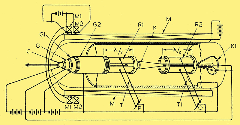
Electrode arrangement of velocity modulator-generator.
The figure shows the electrode arrangement of a 'velocity modulator' for amplifying or generating very high frequencies. The cathode C is followed by two conical control elements and a cylindrical electrode G2, all carrying increasingly positive potentials. These are followed in turn by two 'split' half-wave resonators R1, R2, with an intervening conical collector K. At the far end of the tube is a terminal collector K1 consisting of a disc with radial conical vanes. The tube is surrounded by a main magnetising coil M, with two auxiliary coils M1, M2 placed near the gun or cathode.
In the ordinary way the electron stream from the cathode would pass through the tube as a straight beam. The external magnetic field, however, imparts a spiral motion to the electrons so that they 'fan out' and enter the electrode G2 as a hollow rotating cylindrical stream. Input current is applied across the two halves of the resonator R1 from P through a. transmission line T. If the applied currents are of the same frequency as the periodicity of the rotating stream, some of the electrons will be accelerated and others will be retarded. Certain of the latter will follow a path of diminishing radius and are collected by the conical electrode K. The rest will form a 'bunched' stream of varying density, and will deliver power to the resonator R2, which is coupled through a transmission line T1 to the output O. If the latter is back-coupled to P, persistent oscillations will be generated. The residue of the stream is collected at K1, any undesirable secondary emission being trapped between the vanes.
Marconi's Wireless Telegraph Co, Ltd. (assignees of I Wolff). Convention date (USA) July 21st, 1939. No. 542182.
|