|
How they were developed for Radar.
The first radar PPI (Plan Position Indicator) to be used by the RAF was designed by the authors in 1940, and in view of the use since made of this device it may be of interest to recall early experimental work on radial time bases.
The possibility of the desirable PPI presentation of radar echoes had been realized by the pioneers in the early days of radar. It was not, however, until 1939/40 that the two developments of a radar station using a sufficiently narrow beam and the cathode ray screen with bright and lasting afterglow led to the development of a satisfactory PPI.
In 1939/40 work was proceeding on the design of a 'radio lighthouse' on a wavelength of 50 cm. It was envisaged that with the narrow beams then obtained on this wavelength it should be possible to rotate a time base in synchronism with the aerial rotation to give a radar 'map' of all surrounding aircraft. It was decided that the time base should take one of two forms:-
- An inductive or capacitive voltage split of X and Y vectors and recombination on an electrostatically deflected tube.
- A mechanically rotated current time base on a magnetically deflected tube.
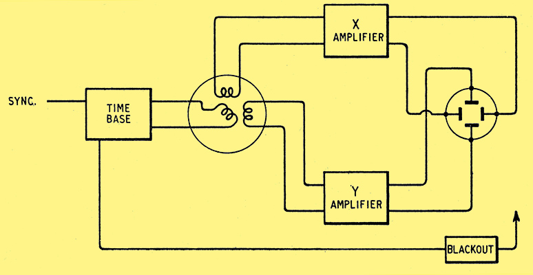
Fig. 1. Schematic circuit of early radial time base.
At that time 12-inch electrostatic tubes were in use on CH and CHL sets and magnetic after-glow tubes were not fully developed; it was therefore decided to adopt the first scheme. A schematic diagram of the arrangement is given in Fig. 1. A resistance-capacity phase shift oscillator (600/800 Hz) was used as a master sine wave generator (see circuit diagram Fig. 2).
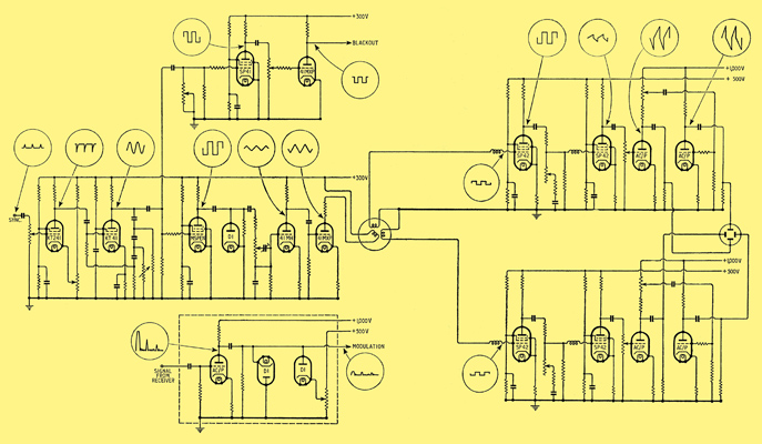
Fig. 2. Complete circuit diagram of radial time base.
The output was squared and then integrated by an RC combination and the resultant triangular wave was amplified and fed to the search coil of an inductive type of phase splitter wound to an accuracy of half a degree. By using a triangular wave, all unwanted inductive effects due to fly-backs were eliminated.
As the induced voltage on the stators was proportional to the rate of change of rotor current, the voltage on the stators was the differential of the triangular wave and a small square wave was induced in each of the stators. The amplitude of these waves rose and fell according to the position of the rotor coil.
Two similar amplifiers X and Y were provided. Taking one amplifier, the incoming square wave was amplified and integrated to a triangular waveform and then mixed with a square wave to give a sawtooth wave form which was equal in positive and negative directions. One of these halves was blacked out on the CR tube so that a single time base trace was left commencing at the centre of the tube. The mixing of triangular and square waves was effected simply by inserting a resistance in series with the integrating capacitor. The square-topped current wave produced a triangular voltage wave across the capacitor and also produced a square voltage wave across the resistance. As both were inserted into the grid circuit of a valve the required mix was obtained.
The resultant waveform was then amplified and passed to two paraphase valves to feed the X and Y deflector plates of the tube. The signals from the receiver were DC restored before feeding to the tube cathode and a diode limiter was also used to prevent defocusing of the tube by large signals. It is interesting to recall that the first model of the rotating time base with tube, time base, power packs, etc., filled the whole of a 6 ft Post Office Rack.
By the time the radial time base was completed (May, I940) the remainder of the 50 cm 'Radio Lighthouse' was not ready, and it was therefore decided to try out the system on the CHL receiver. The CHL set operated on 1.5 metres and was provided with two display tubes, one for range and one with a 'split' device which provided accurate azimuth. It was necessary to stop and 'inch' the aerial system to take an accurate azimuth reading on one aircraft and other aircraft on different azimuths might be missed. A radial time base would provide constant 360 ° cover if a tube with a long afterglow was used. Accordingly, the whole equipment was fitted to a standard CHL receiver at Worth Matravers, Dorset, and after initial teething troubles and one or two false 'invasion' alarms the equipment operated satisfactorily. A map of the Dorset coast was drawn on the tube face with a china-graph pencil by the authors, and the first demonstration of the equipment was given to A M Sir Phillip Joubert. It was remarkable that during his visit a convoy was sailing down the Channel and twelve Spitfires were flying overhead making an excellent 'picture' on the CRT face.
Operational results on this equipment provided the ground work for GCI (Ground Controlled Interception) and the radial time base was renamed PPI (Plan Position Indicator). Interception techniques were studied as the enemy night bombing raids were then just starting. As the width of the aerial lobe was approximately 15°, the echoes were seen as arcs, the aircraft position being the centre of the inner edge.
At this period magnetic tubes with increased beam currents were becoming available and it was decided that, for full production, mechanically rotated time base coils would be simpler to produce, and a PPI of this type was, therefore, designed. A triangular waveform was again used to reduce flyback effects and to simplify scanning transformer design. PPIs of this type were modified for production by the manufacturers.
This type had one main draw-back; it was not automatically self-centring. In order that the time base should rotate about its one end, it was obviously necessary for there to be zero current in the deflector coils at that point. But, as the triangular waveform was fed to the coils through a transformer, the zero current point occurred in the middle of the sweep, and the time base rotated around its mid-point.
To make it rotate around one end, a 'shift' current had to be passed through the coils equal in value to the peak alternating current. This involved a large DC power supply and high-wattage potentiometers for adjusting the shift current; also, it was found that fairly frequent readjustment of shift current was necessary, due to power supply voltage variations, etc. The automatically self-centring circuit of Fig. 3(a) was therefore developed, and was used in the highly mobile Light Warning Equipment and in several ground equipments.
A square wave was applied to the grid of the valve V1, which had the deflector coils in its cathode circuit. During the negative half-wave the valve was cut off therefore no current flowed through the coils and the cathode beam took up its no-current position in the middle of the tube face. During the positive half-wave the valve took current, and, acting as a cathode follower, maintained constant voltage across the coils. Constant voltage across an inductance required constant rate of change of current through the inductance, therefore the cathode beam traced out a linear time base starting from the no-current point on the tube.
The valve was cut off during the periods between time base, and therefore the mean current was very much less than that of the previous circuit.
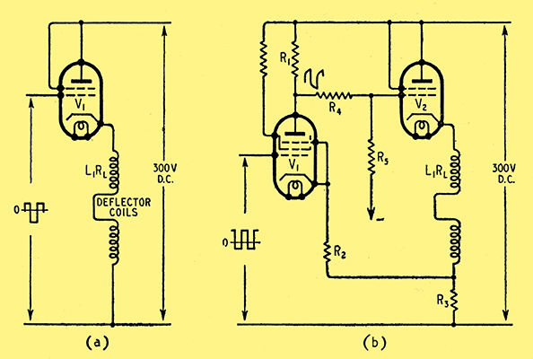
Fig. 3. (a) Automatic self-centring circuit, (b) modified circuit to correct non-linearity in the trace.
The simple circuit of Fig. 3(a) did not give a perfectly linear trace, due to the fact that the deflector coils had resistance RL, and the valve had a finite output impedance. The latter was equal to 1/g where g was the mutual conductance of the valve, and this was about 150 to 200 Ohms for the type of valve used. The effect of this impedance was, at any instant, to decrease the voltage across the inductive part of the coil impedance by an amount equal to the current at that instant multiplied by the resistance (RL + 1/g), this reduced the rate of rise of current in the coil by an equivalent amount.
In order to overcome this effect it was necessary to raise the grid voltage by an equal amount, and this was done automatically in the circuit of Fig. 3(b). A square wave was applied to V1 grid and this appeared inverted on the anode of V1, and finally on the grid of V2, which had the deflector coils in its cathode circuit. These coils had in series with them a total resistance (R1, + R3 + 1/g). Therefore, for a linear time base, it was necessary to add to V2 grid voltage, at any instant, a voltage equal to the current, i, through the coil multiplied by (RL, + R3 + 1/g). This was done by feeding back the voltage iR3 which appeared across R3 into the cathode circuit of V1 and choosing the values of R2, R1, and R4, R5 so that total gain round the circuit from the junction of R2 and R3, through V1 to the junction of R4 and R5 was equal to (R2 + R3 + 1/g) / R3. To a high degree of approximation, this occurred when R1R5/R2 (R4 + R5) = (RL + R3 + 1/g)R3.
This improvement in the circuit came too late to be adopted in the production models of Mark VA or Mark V1 GCI or CHL or in the Light Warning Set, and was, therefore, never used in the field.
Experimental work was also carried out on 'strobing' a portion of the time base shown in Fig. 1, amplifying it and feeding it to another tube. By this means an enlarged PPI was developed. A dim 'square' (approximately) 1 in side on a 12 in tube) was produced on the first tube by partial blackout to identify the area which was being enlarged and this area appeared as full size on the other tube. Owing to the 15° beam-width of the polar diagram the system was not used, but it is interesting to record that a system of this type was operating in this country in I941.
The PPI was next adapted for use in the first centimetre A1 equipment and afterwards for H2S and ASV. It has become one of the most widely used presentation systems for radar both in this country and USA and it seems a far cry from the original 6 ft rack to the compact, efficient airborne PPI's in use today.
| 