|
Ion and Plasma Propulsion
Newton's law of motion that the force on a body is given by the rate of change of its momentum becomes, for an isolated body like a rocket, that the force is given by the rate of loss of mass in the exhaust multiplied by the exhaust velocity the rate of loss of mass, of course, determines the total mass of propellent material which must be carried in the rocket. Thus the propellent mass can only be reduced by increasing the exhaust velocity.
An upper limit to the exhaust velocity is set in chemical rockets when the chemical reaction which gives the greatest energy release is utilized. Unfortunately, even with this maximum exhaust velocity, most of the mass of the rocket has to be taken up with fuel.
Somewhat higher exhaust velocities than are possible with chemical rockets should be obtainable by heating the propellent in other ways, such as for example, by a nuclear reactor, focused solar radiation or electrical arc or RF heating. However, the limit set by the melting point of the most refractory material usable as an exhaust nozzle or propellent container prevents any very great increase in exhaust velocities being obtainable by such alternative methods of heating the propellent.
The power consumed in the exhaust is proportional to the square of the exhaust velocity (for a given rate of loss of propellent mass), whereas, as we have seen, the force on the rocket is proportional only to the first power of the exhaust velocity. Now the power consumed will, of course, determine the mass of the power plant required. Thus, as the exhaust velocity is increased, the mass of the power plant required tends to increase much faster than the force on the rocket. Even when the decrease in the propellent mass required as the exhaust velocity is increased is allowed for, the total mass of the rocket tends to increase faster than the force on it. Hence, as the exhaust velocity is increased, the acceleration of the rocket tends to decrease. This decrease is, in fact, confirmed when particular propulsion processes are considered.
The acceleration required to leave the earth and achieve a satellite orbit can in fact only be achieved by means of chemical or nuclear reactor propulsion. The acceleration required to proceed beyond a satellite orbit is, however, very much less than the acceleration required to attain such an orbit. With the recent achievement of satellite orbits, other low-acceleration methods of rocket propulsion thus come into practical consideration. As we have seen, low-acceleration but high-exhaust-velocity propulsion systems allow an advantageous decrease in the proportion of the mass of the rocket which must be taken up by the propellent.
Propulsion systems offering exhaust velocities higher than are feasible using chemical or other methods of heating the propellent usually fall into one of two general types: the propellent is either in the form of ions which are accelerated by an electrostatic field, or it is in the form of neutral but fully ionized gas (plasma) which is accelerated by the force produced by a magnetic field on currents driven through the plasma.
Ion Propulsion
Nozzle heating limitations will not apply here, provided that interception by the electrodes of the ions is kept very small by accurate focusing.
To produce the maximum thrust for a given electric power, the mass to charge ratio of the ions should be as large as possible. One simple way of producing ions with a high mass to charge ratio is to cause the vapour of an alkali metal (such as caesium or rubidium) to come into contact with a hot surface made of a material (such as tungsten, platinum, molybdenum or tantalum) whose electron emission work function is greater than the ionization potential of the alkali. Nearly all of the alkali atoms will then be ionized, provided that the temperature of the hot surface ionizer is greater than a certain critical value.
Advantages of this method of ionization are the freedom from erosion and thus long life of the ionizer, the high proportion of the alkali atoms ionized, and its simplicity and reliability. The principal power loss in an ion propulsion motor employing this method of ionization is that consumed in heating the ionizer.
If the alkali vapour is simply passed over the hot surface or the ionizer then the incoming un-ionized alkali vapour will scatter and thus defocus the acceleration ions. This difficulty can be resolved by making the hot ionizer porous so that the alkali vapour can diffuse from beneath the hot surface. It can be shown that with this arrangement hardly any neutral alkali atoms will leave the pore outlets, provided that the pores are made sufficiently small. To prevent ion interception with consequent secondary emission, erosion and heating at the accelerating electrodes, very good focusing of the ion beam is necessary. A collimated beam is also desirable to maximize thrust. At this focusing accuracy, owing to space-charge defocusing effects, the required beam currents cannot be obtained in a single beam. A number of parallel beams will thus probably be required.
The ion beam must be neutralized after it has been accelerated, otherwise the rocket will charge up until no further ions can be ejected. An obvious way of neutralizing the ion beam is to use a thermionic emitter to inject electrons into the ion beam with the same vector velocity as the ions. Unfortunately, complications are produced because the electron velocities due to random thermal emission and to radial attraction towards the positive ion beam are then comparable or greater than the required velocity. The heater power lost in producing sufficient electrons from the thermionic emitter is a very small fraction of the ion beam power.
One suggested design of ion motor is described by A T Forrester and R C Speiser in the October 1959 issue of Astronautics (page 34), and a schematic of this design is shown in Fig. 1.
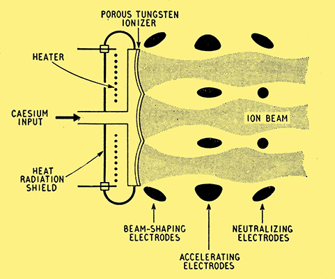
Fig. 1 Schematic of proposed ion propulsion motor. (Based on a figure in an article by A T Forrester and R C Speiser in the October 1959 issue of Astronoutics.)
Here caesium ions diffusing through porous tungsten are used. The tungsten ionizer surface is specially curved to help focus the strip ion beams. Electrons are thermionically emitted from part of the surface of the neutralizing electrodes. These electrodes are also made positive with respect to the accelerating electrodes. This prevents neutralizing electrons from bombarding the tungsten, although it also results in some deceleration of the positive ions. Heat radiation shields are provided to reduce radiation losses from the hot tungsten ionizer.
Plasma Propulsion
Container and nozzle heating can be reduced in this system either by using magnetic fields to keep the plasma ions away from the walls or by linearly moving the plasma as far as possible rather than merely heating it. Space-charge defocusing limitations which arise in ion propulsion are avoided by using plasma because the ion and electron densities are then everywhere essentially equal.
In plasma propulsion it is possible to consider the forces produced by magnetic fields on currents driven through the plasma in two ways, either from a large- or from a small-scale. point of view. From a large-scale point of view, the force produced by a magnetic field on a plasma current is given in magnitude by Amperes law and in direction by Flemings Left Hand Rule. In practical propulsion systems the magnetic field is often produced by the plasma current itself. The driving force is also often due to a difference between the magnetic fields on opposite sides of the plasma caused by curvature of the plasma current. Plasmas are also such good conductors that they are almost entirely prevented from crossing magnetic fields by the forces produced by interaction between these fields and the back EMFs set up in the plasma according to Lenzs law. Plasmas can thus be propelled by moving magnetic fields, and in some devices such fields are produced by the sudden increase in plasma current at the beginning of a discharge.
From the small-scale point of view, the inability of plasmas to cross magnetic fields may be considered as being due to the fact that linear electron and ion motions become curled up on themselves into small cycloids by the action of the field. Plasmas also find it difficult to enter strong magnetic fields even by travelling along the field lines. This is because as the field increases more of the energy of linear motion of the ions and electrons becomes converted into energy of rotation about the field lines and the linear motion decreases. Because of this tendency to drift from strong to weak magnetic fields, plasmas behave rather like diamagnetic substances.
Losses in plasma rockets can arise in three places: at the electrodes, in the plasma itself, and at the plasma container walls.
Electrode losses may be produced in the voltage drops near the electrodes which are often associated with gas discharges. The relative importance of these losses can be reduced by ensuring that any such voltage drops near the electrodes are small compared with the voltage drop in the main body of the plasma. Fortunately, even though plasmas have a low resistance, this can be done without having to pass impossibly high currents because of the back emf produced by interaction between the moving plasma current and the magnetic field.
Losses in the plasma itself can occur due to ion recombination and cooling. The relative effect of these losses can be reduced by as far as possible directly linearly moving the plasma rather than merely heating it.
Losses to the container walls can be shown to be relatively more serious than in ordinary chemical rockets since in plasmas the power levels and densities are lower. However, these losses can be very much reduced by using magnetic fields to keep the plasma away from the walls.
The magnetic field required for reacting on the plasma current may be obtained in two ways, either directly as the field due to the plasma current itself, or from an external source. The latter method of obtaining the magnetic field is less preferable because of the extra mass and electrical heating losses in the field coils, though an ingenious suggestion for reducing the electrical loss is to make the coils super-conductive by cooling them by exposure to outer space.
Motion due to magnetic fields generated by the plasma current itself occurs in transient rather than steady state conditions. An obvious way of obtaining the required transient currents is by discharging a capacitor through the plasma. The construction of this capacitor then presents a number of problems, since it should have a low mass, high energy storage capacity, low loss, permit rapid and continual cycling, and be very reliable. Another problem likely to arise if transient discharges are used is that optimum pulse repetition rates are usually at audio frequencies, and such frequencies may produce fatigue in the rocket structure and possibly discomfort to a rocket crew.
A considerable number of plasma propulsion methods have been experimented with but most of these methods fall into one of two classes: a straight discharge in which the plasma motion is at right-angles to the discharge, or a contracting discharge in which the plasma motion is at right-angles to the direction of contraction.
A very simple type of straight discharge producing motion at right angles to the discharge may be obtained between the ends of two wire electrodes protruding from an insulator. An externally provided magnetic field parallel to the wires can be used to confine motion to this direction. Alternatively, an external field at right angles to the plane of the two wires can be used to accelerate the discharge. In this case the insulator is dispensed with and the discharge starts between the ends of the two wires connected to the current supply and is accelerated by the field along the wires to their other ends. This rail accelerator, as it is called, should pulse itself due to the ejection of one plasma permitting the input voltage to rise until another discharge is struck.
Another type of straight discharge producing motion at right angles to the discharge can be obtained in a T-shaped tube. The discharge is struck between the ends of the (normally) horizontal arm of the T and plasma is then ejected down the vertical arm. Extra acceleration of the plasma can be produced by an externally-provided magnetic field perpendicular to both arms. Such a field could, for example, be produced by the return current from the discharge flowing in a suitably oriented coil.
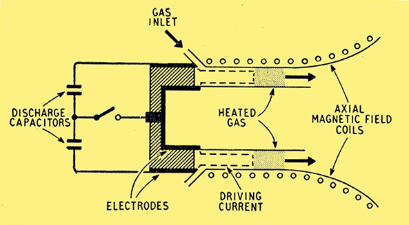
Fig. 2 Schematic of one proposed type of plasma shock propulsion motor. (Based on Fig. 7 of an article by M Camac, A Kantrowitz and H E Petschek in the April I959 issue of IRE Transactions on Military EIectronics.)
Fig. 2 shows schematically a propulsion system described by M Camac, A Kantrowitz and H E Petshek in the IRE Transactions on Military Electronics for April, 1959 (p. 39). This system utilizes a more complicated form of discharge producing motion at right angles to the discharge. Here the discharge is struck between two concentric cylinders and thus initially forms an annular sheet. As the discharge current grows, however, the path it takes expands down the space between the cylinders driving the gas in front of it (see Fig. 2). About half the energy goes into linearly moving the gas and half into heating it, some of the latter energy being recovered when the gas expands near the outlet. A weak externally-provided magnetic field along the cylinder's axis reduces plasma flow to the walls. Alternatively, a strong axial magnetic field may be used. This produces rotation of the plasma about the cylinder's axis which is then converted into motion along this axis as the gas expands near the outlet. In this modification, since the initial velocity of the plasma along the axis is lower, it spends a longer time in the initial accelerating region. The peak input power required is thus reduced. In this modification the gas is injected radially at the inner rather than the outer cylinder.
One type of contracting discharge may be produced in a discharge tube round which is wound a single-turn coil. A rapidly-increasing current in the coil produces an electric field which breaks down the gas in the tube to give circular discharge currents in the opposite direction but parallel to that in the single turn. The current in the coil also produces a magnetic field along the discharge tube axis which drives the plasma inwards towards this axis and thus propels the plasma along the tube.
Another type of contracting discharge is the cylindrical pinch discharge struck between two facing disc electrodes. This produces a contraction towards the cylinder axis due to the attraction between the various like currents out of which the discharge may be regarded as being composed. If a hole is made in the centre of one of the electrodes, the compressed plasma will be forced out through this hole along the cylinder axis. In practice the disc electrodes may be shaped to further direct the flow.
Thermonuclear reaction propulsion is somewhat similar to plasma propulsion in that magnetic fields are used to direct the ionized reacting material in this case away from the reacting walls. One possible system utilizes the contracting cylindrical pinch discharge just discussed, the reacting material being heated by the discharge current. Other systems necessitate heavy magnetic field coils.
Advantages common to both plasma and ion rockets are the possibilities of exactly controlling the thrust and of using the power source (which in these systems is electrical) to supply the radio transmitter when the rocket motor is switched off.
The highest possible exhaust velocity is achieved when light is emitted as the exhaust. Calculations show, however, that the thrust achievable with light will not be capable of providing anything like even the small acceleration required for proceeding beyond a satellite orbit.
References
- IRE Transactions on Military Electronics, April, 1959.
- Astronautics, October, 1959.
- Electronics, April 24, 1959, pp. 69-71.
|