|
A New Marconi-Osram Table
A new table specially designed for conditioning and testing Osram N339 and U329 valves has been developed by the Marconi-Osram Valve Co., Ltd. Both types are used in domestic television receivers, the N339 as a line output-valve and the U329 as a booster diode with exceptionally high heater-cathode insulation. The new table subjects them to the same high peak voltage and currents as they encounter in service, and ensures a uniform high standard of performance.
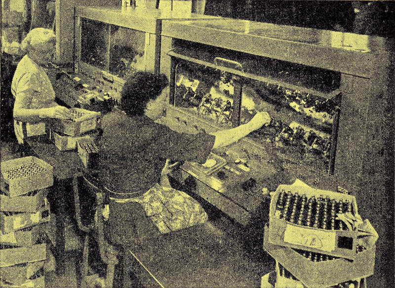
Two of the new tables are shown in the illustration. Each of them incorporates twelve test positions which will accommodate either type of valve. The valves are inserted and a Perspex window is drawn down over them.
The peak voltages developed on the valves can then be increased from zero to maximum either manually or automatically to a preset sequence. Each valve is monitored by pressing the button located immediately below it, the peak output voltage being indicated on a meter let into the front of the table.
Circuit Details
The test circuit for each valve is very similar to the line time-base circuit used in television receivers. The line transformer is loaded with a dummy coil to simulate the effect of the deflection coils. All twelve test positions are driven by a negative 10kHz pulse at the grid of the N339 from a common driver unit, the output of which is kept at a constant amplitude.
The peak voltage developed on the anode of the N339 is dependent on the rate of change of current through the valve at cut-off. The current flowing through the valve is controlled by a variable screen grid supply which, therefore, controls the peak voltage output.
The automatic conditioning is achieved by providing a stepped input voltage to the screen grid power supply from a thyratron operated timer unit. The number of switched steps available is 24 and the duration of each step is variable over a considerable range by adjustment of the thyratron circuit. The maximum screen grid voltage may be preset by a control on the front of the desk.
After the conditioning process is completed the equipment may be set up for testing the valves. The valves are switched on cold and the peak voltages are allowed to build up quickly to the maximum rating. This is the treatment the valves receive in a television receiver and the conditioning process ensures that no flashing will take place during testing and use.
|