|
The transmitter from which test programmes were broadcast in February, 1922, from the Writtle establishment of Marconis Wireless Telegraph Company Limited is frequently mentioned in correspondence and it has occurred to me that you may be interested to have an authentic description of this transmitter for the record. The information will no doubt be of interest when the 50th or 100th anniversary of broadcasting in this country is celebrated.
When the Writtle Experimental Establishment of the Marconi Company was requested to produce a transmitter there was no difficulty in design work. We simply used the standard Marconi radio-telephony transmitting circuit of those days.
At the beginning of the transmissions on the 14th February 1922, the transmitter operated on a wavelength of 700 metres with an approximate power to the aerial of 200 Watts.
The aerial was of the 4-wire inverted L configuration, supported by two 110ft Marconi portable masts and was 140ft long.
2MT Writtle February 14, 1922.
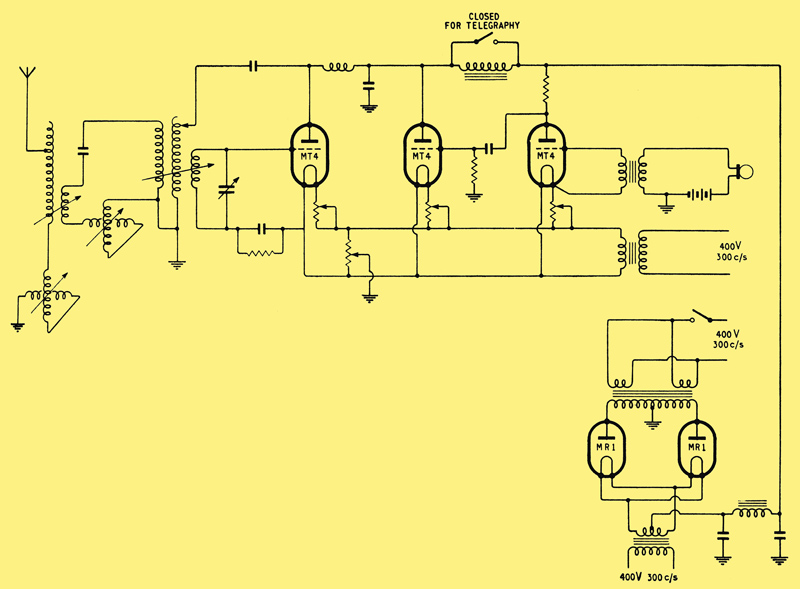
The circuit of the transmitter is depicted in the accompanying diagram. It will be observed that the radio-frequency circuit was of the self-oscillatory variety using a reaction coil coupled to the main tank circuit, the reaction coil being tuned to 0.7 of the operating wavelength.
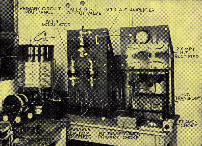
The aerial tuning coil consisted of an ebonite slat former wound with 243/36-stranded cable. This was magnetically coupled to a primary tuning circuit, the inductance of which was wound with 729/44-stranded wire. This inductance is shown on the left of the photograph, and is of interest because it was made under Mr P P Eckersleys direction in 1919 and the stranded wire was actually made on the premises. This inductance was used initially to investigate the application of Mr T L Eckersley's earth screen to medium wave aerials. The closed circuit condenser consisted of a stack of zinc plates separated by ebonite insulators. This was situated under the bench on which the inductance was mounted.
In order to obtain the correct anode impedance, a tightly coupled secondary winding, consisting of a coil of No. 20 gauge wire, was wound over the primary tuning inductance.
The circuit was shunt connected to one MT4 triode, which was a standard Marconi valve at the time. Amplitude modulation was effected by a Heising circuit, one MT4 being used as a modulator and another as an amplifier. In the first few transmissions the microphone was directly connected to the grid of this valve.
The anode high tension, at 8,000 Volts, was supplied by two MR1 valves in bi-phase connection. The valves and high tension transformer are also shown in the photograph.
The primary supply to the HT transformers and the filament transformers was supplied by a 400 Volt, 300 Hz, single-phase alternator, driven by a 110 Volt DC motor which received its supply from two 4.5 kW, 110 Volt, petrol (4 cylinder Austins) motor generators.
For the first few months, morse was transmitted during a proportion of the programme time for the purpose of providing calibrating signals to amateurs. Keying was effected by interruption of the HT transformer primary circuit by a standard Marconi morse key. This key is shown in the lower left of the photograph.
The valves and other components were mounted on two panels obtained from a dis-used CW transmitter.
The circuitry was precisely similar to that designed by Mr P P Eckersley for the ground station transmitter installed at Croydon Aerodrome in 1920. The transmitter was very simple compared with others under development at Writtle at that time and, initially, it was got going within an hour.
Unfortunately, while the Heising modulation circuit was suitable for high-quality reproduction, the only valve available at the date of commencement of service was the MT4 which we realized would not be capable of providing reasonably good quality, even for those days.
After one or two transmissions, a microphone amplifier was used in place of the MR4 amplifier and three MT4 valves with the grids biased positive were used in an effort. to obtain linear working. Unfortunately, it was not possible to obtain sufficient dissipation at the anodes of these valves to provide Class AB working. In the meantime, N (later Sir Noel) Ashbridge and H L Kirke were working on the problem and devised the characteristics of suitable valves which were developed by the M O Valve Co. These were delivered in a remarkably short time and three were used in parallel, operating in the Class A mode.
The components from which the transmitter was built were mainly supplied from our experimental stock in trade. Any suggestion that we were wildly searching for components or struggling to make the transmitter work is simply not correct. If we were short of anything the Marconi laboratories and works at New Street, Chelmsford, supplied our wants within the hour.
The physical assembly of the transmitter was carried out by the workshop mechanics, F Bubb and J Russell.
The limitation was then the Peel Connor carbon microphone which was used throughout the transmissions. Unfortunately, no other type of microphone was available until Captain Round produced the Round/Sykes microphone in 1923.
On the 29th May 1922 the wavelength was changed to 400 metres and the transmission of morse calibration signals was abandoned.
The coupled circuit was dismantled and a plain aerial circuit was adopted, using an aerial tuning inductance wound with 81/44-stranded cable. This coil was tightly coupled to a secondary winding, known as the 'ratio winding' patented by Eckersley in 1919.
The transmitter circuit remained in this condition until the final transmission on the 17th January 1923.
It is unfortunate that on the cessation of transmission in January 1923 the equipment was dismantled and the parts returned for normal experimental work. All has been lost with the exception of the 6 kW motor generator which the writer found under a tarpaulin in a field at Writtle a few years ago. This he purchased from the Marconi Company, dismantled, dried out and made to work. In due course it will be presented to the Marconi museum.
Chelmsford, Essex. B N MacLarty
Engineer-in-Chief
Marconis Wireless Telegraph Co Ltd.
|