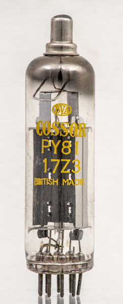
The PY81/17Z3 was specifically built as an efficiency diode for television line scan and the design dates to the early 1950s. Considerable energy is fed to the line deflection coils and this has to dissipate during flyback. The efficiency diode channels this energy back to the supply rail smoothing capacitors for use on the next line scan.
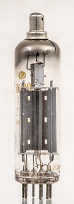
The Mullard advert gives details of the construction. The mica discs are coated to improve insulation, the cathode is made from nickel alloy and the anode is a copper laminate.
This rectifier is specified as having a peak inverse voltage rating of 4,500 Volts, and a peak current rating of 450 mA. See PY81 for details of the materials used in the Mullard version.
The anode is opened out at the ends to give a greater radiating area. Note that the black coating is only on the outside - no heat radiation back to the cathode if at all possible.
The anode is stitched together. Difficult to see but the heater is surrounded by an insulated wire helix to increase the heater/cathode insulation. Television receives did not include mains transformers and so the heaters were all wired in series across the supply leaving a very considerable voltage difference between heater and cathode.
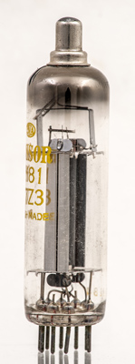
The thin glass tube envelope is 20 mm in diameter and, excluding the B9A base pins, is 73 mm tall.
References: Data-sheet, 3002 & 1040. Type PY81 was first introduced in 1951. See also1951 adverts.