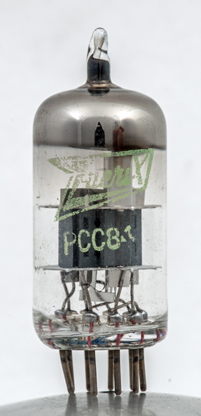
The PCC84 double triode shows how valves developed to meet the needs of the planned VHF television (Band III) transmission that opened in the UK in 1955. It was superseded by the PCC89.
The PCC84 was specifically designed for cascode operation. The normal configuration was for triode one to be operated as a grounded cathode stage directly coupled to triode two. Triode two was connected as a grounded grid stage.
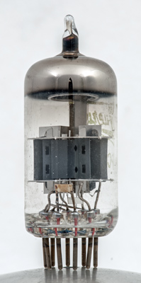
The triode has a smaller inter electrode capacitance than a pentode at VHF and could be made physically small. The photograph shows that within the envelope the electrodes are a small percentage of the total volume. The two triodes would be used for initial signal amplification at up to 220 MHz. The low anode voltage and relatively high current being features to ensure low noise operation. The anode dissipation was two Watts for one triode or 2.5 Watts for both triodes operating.
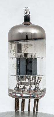
The triodes are separated by a Z shaped screen with additional screens above and below the mica discs.
The shape of the anode is a flat plate with a rectangular box in the centre. The two parts are stitched together.
The thin glass tube envelope is 20 mm in diameter and excluding the B9A base pins has a length of 48 mm.
References: Data-sheet & 1040. Type PCC84 was first introduced in 1953. See also1953 adverts.